
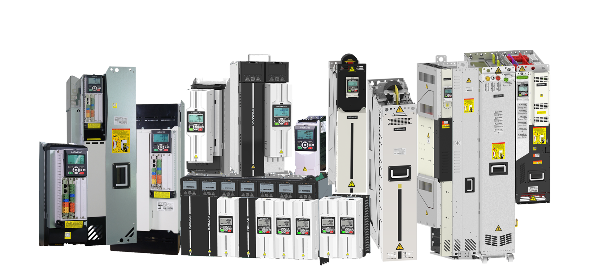
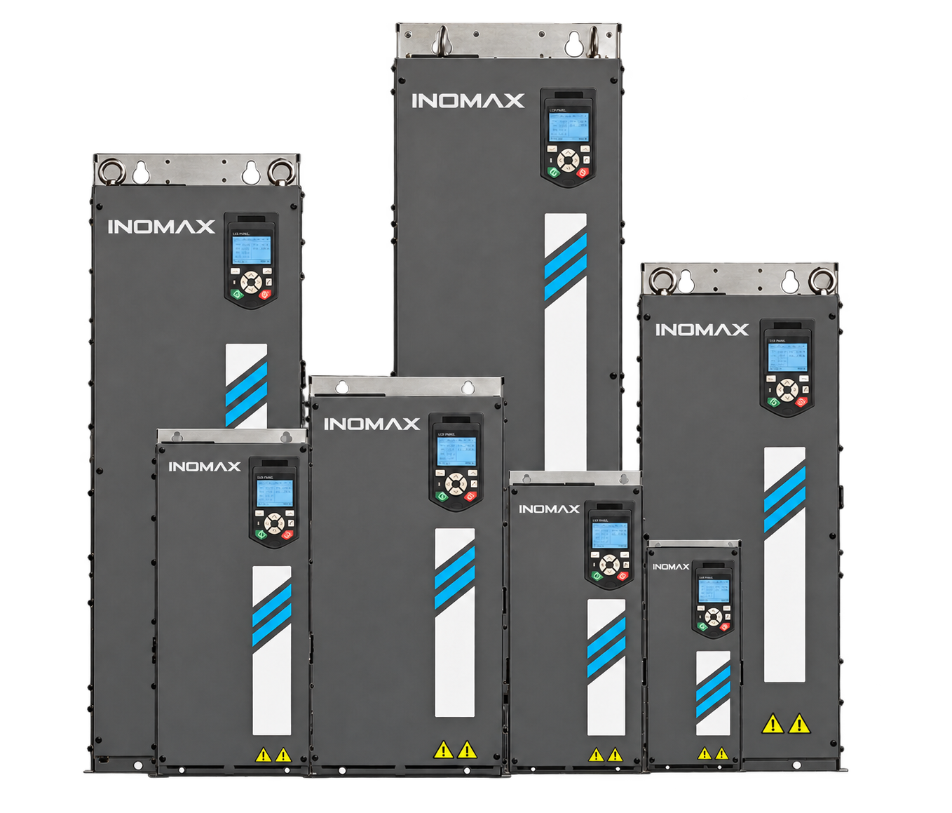
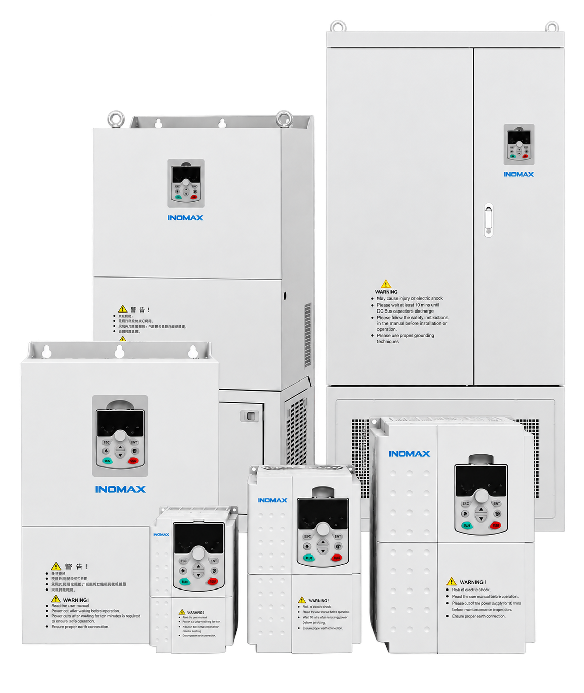
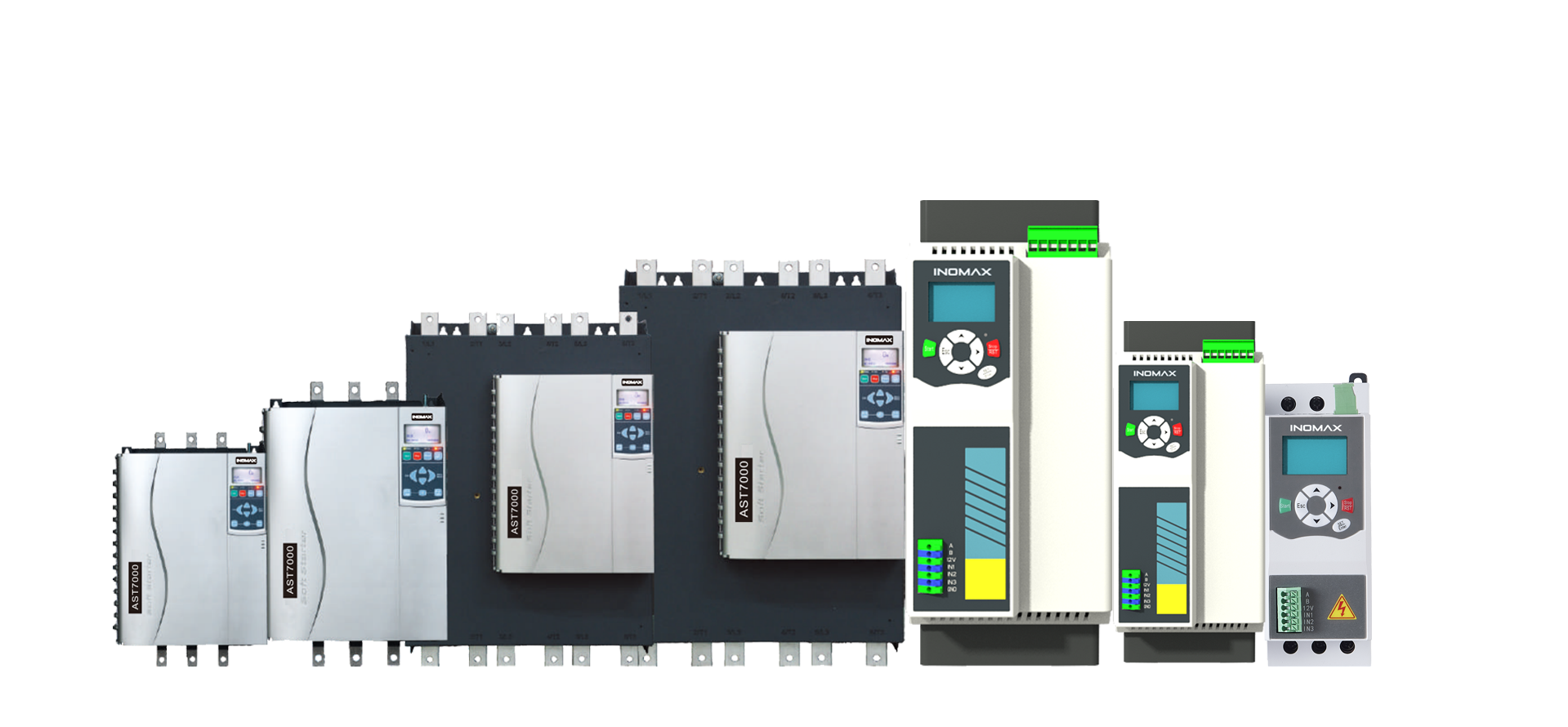
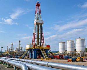
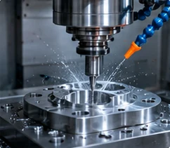
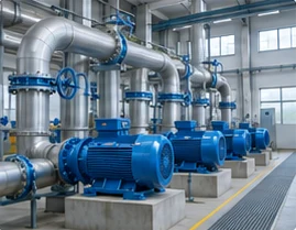
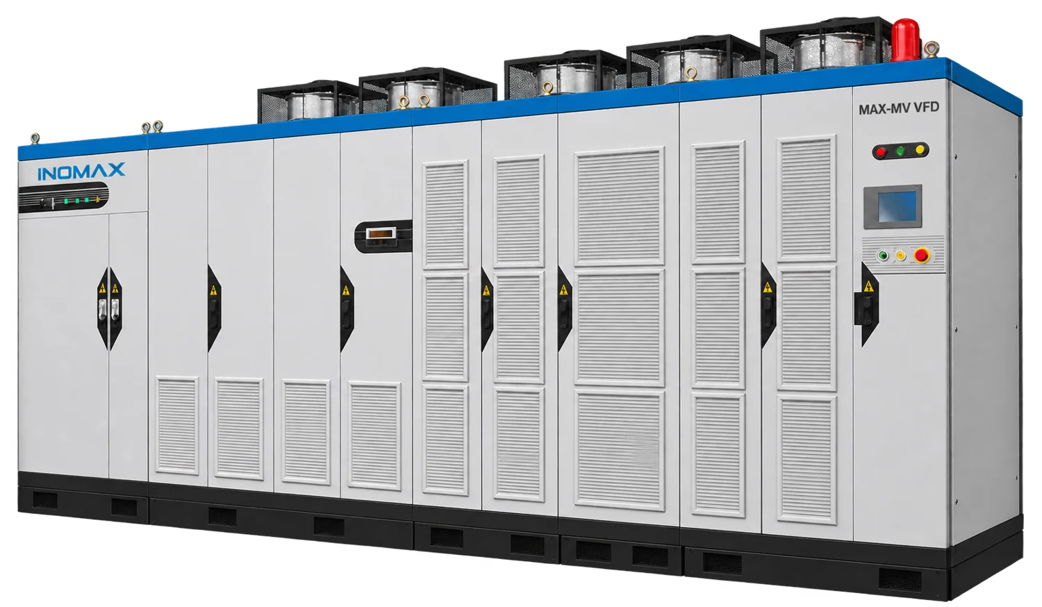
*High-power and 13.8 kV configurations require project confirmation. The standard published model ranges are listed below.
Find the right drive for your project.
Explore ten focused guides by motor voltage, power, cooling, application and project scope. Each guide includes selection data, engineering considerations and practical answers for your team.
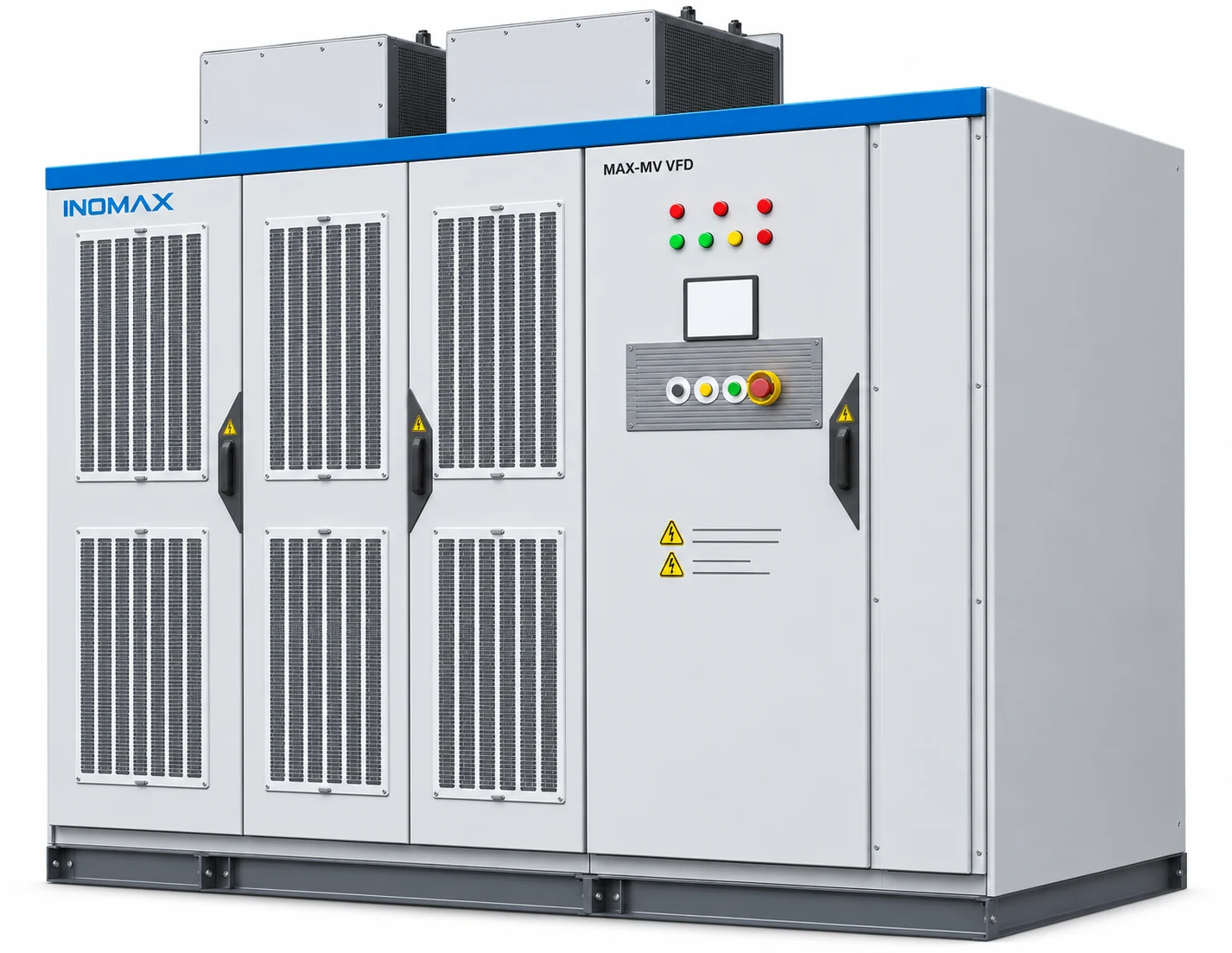
3 kV, 3.3 kV & 4.16 kV Drives
Compare 77 selections by voltage, motor current and cabinet dimensions.
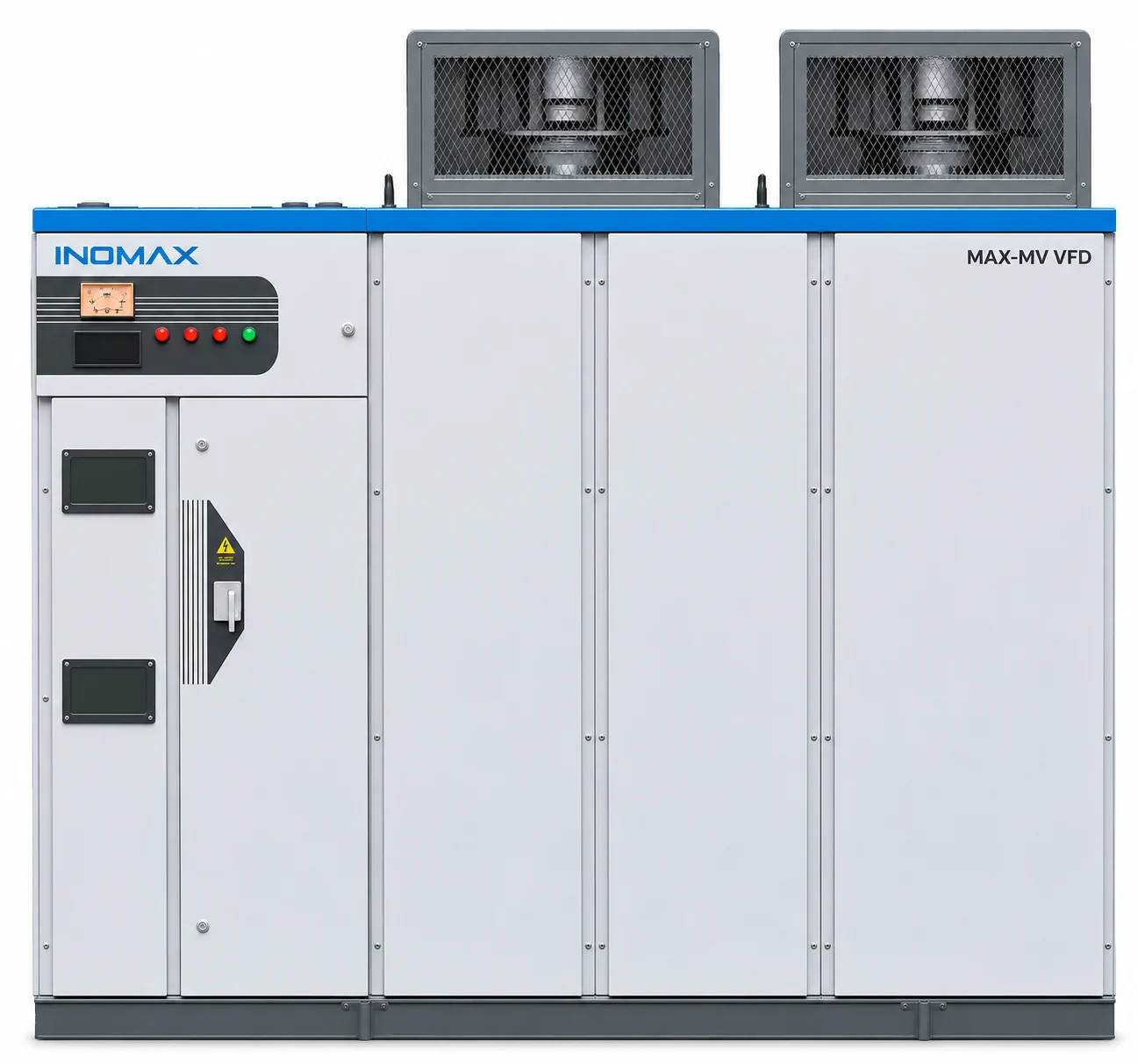
6 kV & 6.6 kV Drives
Explore 64 selections for large industrial motors and site integration.
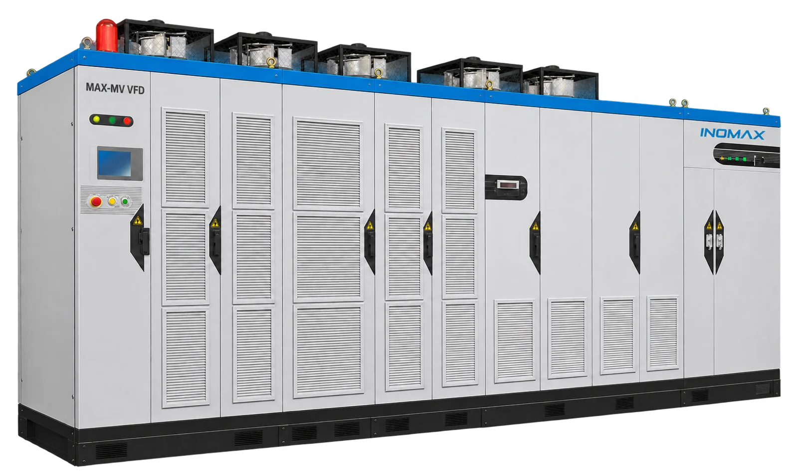
10 kV, 11 kV & 13.8 kV Solutions
Review standard 10/11 kV models and project-engineered 13.8 kV systems.
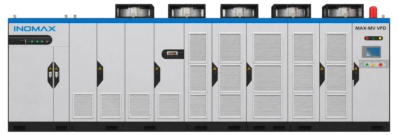
1–10 MW Drive Selection
Plan high-power projects around current, duty and installation limits.
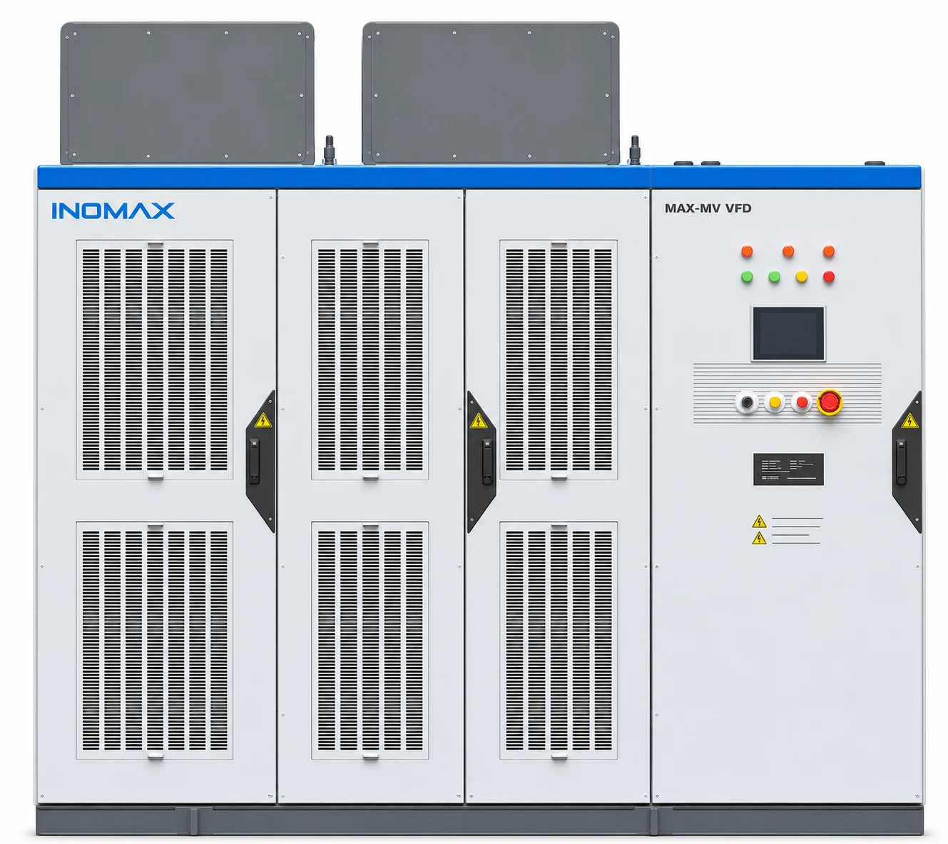
Air Cooling & Water Cooling
Compare room ventilation, heat removal and engineered water circuits.
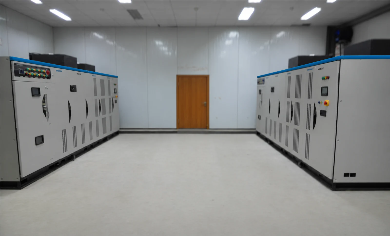
Pumps & Water Treatment
Match the drive to pump duty, operating flow and pressure control.
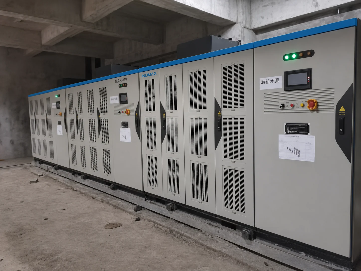
Industrial Fans & Blowers
Review fan starting, flying start, speed limits and process control.
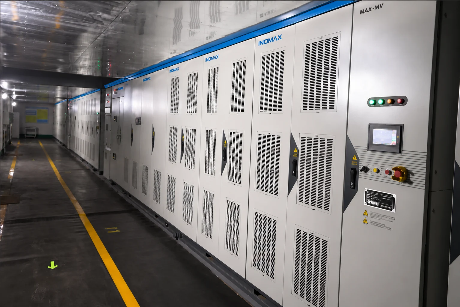
MVR & Process Compressors
Address compressor starting torque, speed windows and process interlocks.
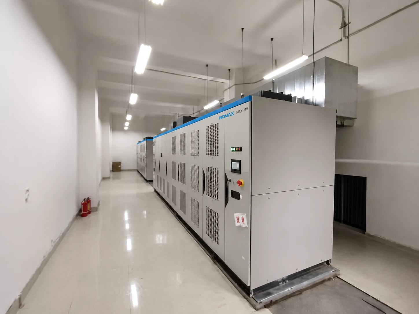
ABB & Siemens Drive Retrofit
Prepare motor compatibility, switchgear interfaces and shutdown planning.
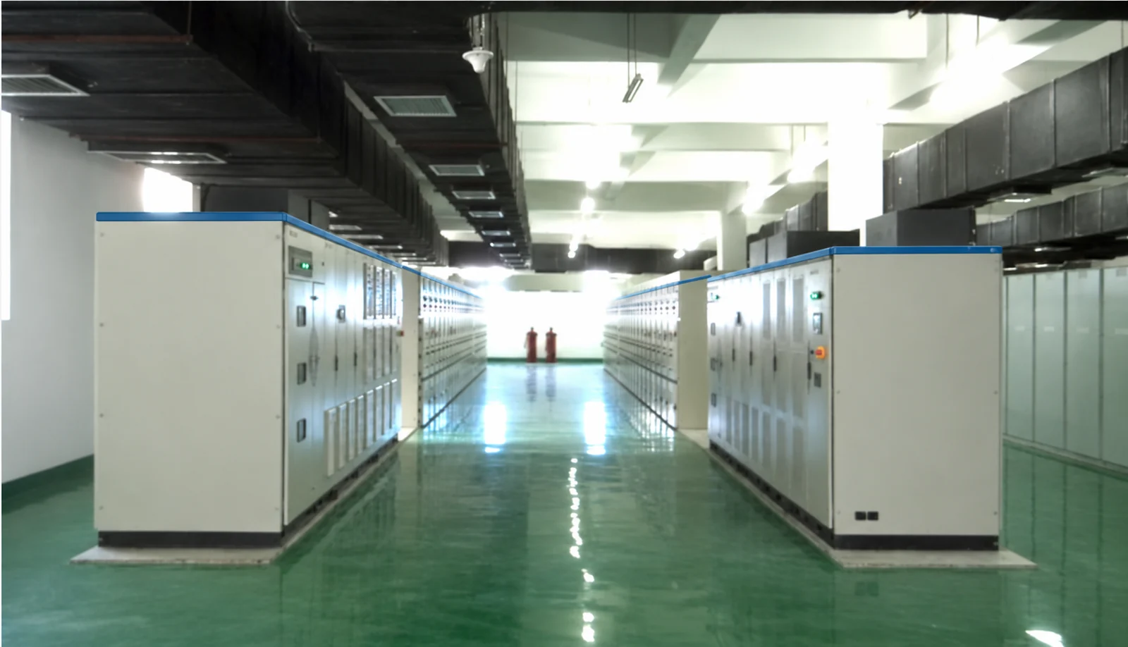
OEM, EPC & Distributor Packages
Build a technical scope, documentation package and service agreement.
One drive platform. A complete engineered system.
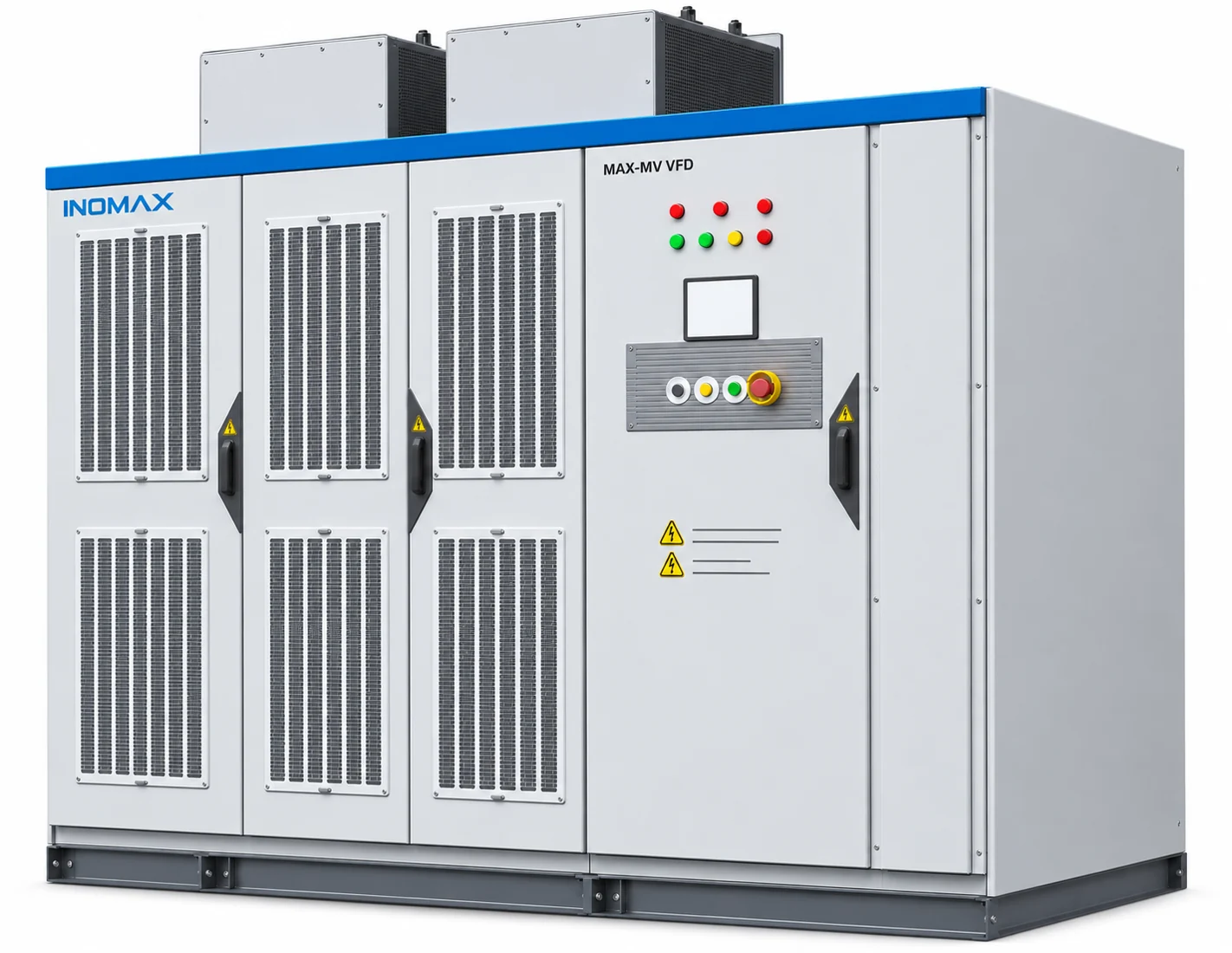
The INOMAX MAX-MV series is a medium-voltage variable frequency drive for controlling the speed and torque of large AC motors. It supports induction, synchronous and permanent-magnet motors in appropriately selected configurations, serving new installations and motor-drive retrofits.
A phase-shifting, multi-secondary transformer supplies cascaded power cells. Their combined output produces the motor’s required medium-voltage waveform. Optical-fibre communication isolates the low-voltage controller from the power stage, while a DSP and FPGA coordinate control, monitoring and protection.
The complete package brings together the transformer, power-cell cabinet, controller and project-selected cooling, isolation and bypass equipment. INOMAX reviews the motor, electrical network and process duty as a system so the final selection fits the installation.
Select the rating around your motor.
Start with the motor nameplate voltage and rated current, then check overload, starting torque, acceleration time and site derating. Motor power alone is not a sufficient selection criterion.
| Motor voltage | Voltage code | Published motor power (kW) | Published current (A) |
|---|---|---|---|
| 3 kV | 030 | 160–3,150 | 39–778 |
| 3.3 kV | 033 | 160–3,150 | 34–722 |
| 4.16 kV | 040 | 160–4,000 | 34–687 |
| 6 kV | 060 | 160–6,300 | 20–780 |
| 6.6 kV | 066 | 160–6,300 | 18–722 |
| 10 kV | 100 | 200–10,000 | 15–725 |
| 11 kV | 110 | 200–10,000 | 14–656 |
Reference selections
Reference selections for initial sizing. Dimensions are length × width × height, in millimetres.
| Model | Motor power (kW) | Current (A) | Cabinet L × W × H (mm) |
|---|---|---|---|
| MAX-MV-030-1000 | 1,000 | 240 | 4200 × 1300 × 2300 |
| MAX-MV-033-1000 | 1,000 | 219 | 4200 × 1300 × 2300 |
| MAX-MV-040-1000 | 1,000 | 170 | 3900 × 1200 × 2200 |
| MAX-MV-060-1000 | 1,000 | 123 | 2900 × 1500 × 2000 |
| MAX-MV-066-2000 | 2,000 | 219 | 3200 × 1550 × 2200 |
| MAX-MV-100-4000 | 4,000 | 290 | 4700 × 1300 × 2200 |
| MAX-MV-110-4000 | 4,000 | 262 | 5300 × 1500 × 2200 |
Top-mounted fans and bypass cabinets are excluded from the tabulated dimensions. An additional 800 mm current-limiting cabinet is required for 6.6 kV ratings from 2,800 kW and 11 kV ratings from 4,500 kW. Always use the approved project drawing for room layout.
How to read a MAX-MV model
MAX-MV-060-1000 identifies the MAX-MV series, 6 kV voltage class and 1,000 kW motor rating. Motor/duty suffixes include T for synchronous motors, PM for permanent-magnet motors and S for heavy-duty selection. No motor suffix denotes an asynchronous motor. Confirm the complete ordering code and suffix combination with INOMAX.
From essential utilities to process equipment.
Water & wastewater
Intake, transfer, circulation and sewage pumps. Process PID adjusts speed to the required flow, pressure or level.
Power generation & heating
Induced-draft and primary-air fans, condensate and circulation pumps, and district-heating pump networks.
Steel, metals & cement
Dust extraction, process-water pumps, kiln and preheater fans, raw-mill ventilation and cooler fans.
Oil, gas & chemical
Pipeline, injection, brine and circulating-water pumps, plus engineered compressor and process-utility duties.
Mining & mineral processing
Mine ventilation, drainage and water supply. High-torque or regenerative duties require a load-specific control and power-stage review.
Compressors & test systems
MVR and process compressors, motor and pump test benches, and engineered variable-frequency test power supplies.
Energy-saving assessment: variable-speed control can reduce throttling and damper losses in suitable fan and pump systems. Actual savings depend on the load curve, static head, operating hours and existing control method; no fixed saving applies to every installation.
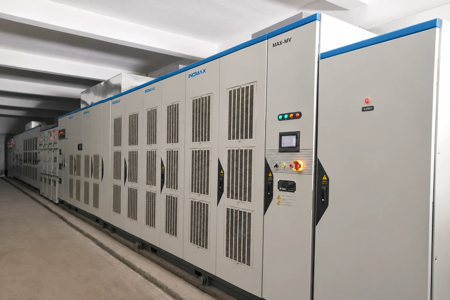
Build around the application
For pumps and fans, focus on the operating profile and process feedback. For compressors, review the permissible speed range, starting torque and process interlocks. For test systems, define output-voltage and frequency requirements, test sequence and measurement interfaces.
Control, protection and options that fit the job.
Configure the drive for the process, control system and required operating continuity. Optional functions and equipment are defined in the project scope.
Motor control, starting and coordinated operation
Choose V/F, V/F with encoder feedback, sensorless vector control or closed-loop vector control. Flying start identifies a rotating motor before resuming control, including forward and reverse rotation. Master–slave coordination supports speed or torque sharing through optical-fibre communication.
Adjustable acceleration and deceleration, torque boost, skip-frequency settings and power-loss restart help match the process. Restart and automatic recovery settings must follow the machinery’s operating and safety requirements.
Process PID and programmable operating sequences
The built-in PID controller supports pressure, flow, level, temperature or tension regulation, with two parameter sets and feedback-limit functions. The simple PLC provides one 32-stage sequence or two 16-stage sequences with configurable frequency, time and acceleration/deceleration, plus cycle, stop and final-speed behaviour.
Power-cell bypass and continued operation
The modular power unit provides electronic bypass, with a mechanical bypass path for the specified configuration. Neutral-point-shift or level-bypass strategies can support continued operation after a cell fault. Available motor voltage and load capability depend on the remaining cells and selected bypass strategy.
Cell bypass is different from transferring the entire motor to the mains. Continued operation and the allowable reduced rating must be agreed for the application.
Line bypass, synchronized transfer and multi-motor arrangements
Project options include manual or automatic line bypass, one-drive/one-motor or one-drive/two-motor arrangements, and variable-frequency starting followed by synchronized transfer. Review grid conditions, switching equipment, interlocks and the external circuit breaker together. A soft-start-and-transfer installation is not the same duty as continuous variable-speed operation.
Grid disturbances, protection and cooling supervision
Low- and high-voltage ride-through functions are coordinated with the process and permitted disturbance envelope. Protection covers overcurrent, overvoltage, undervoltage, phase loss, short circuit, phase imbalance, overheating and motor overload. Cooling supervision includes fan overload, phase loss, contactor faults, temperature monitoring and configured fan-life alarms.
HMI, diagnostics and control-system integration
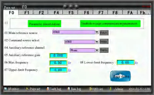
The local HMI displays operating frequency, voltage, current and power, with power-cell status, terminal monitoring and parameter access. Fault records retain relevant operating data for diagnosis. Access levels help separate routine operation from engineering settings.
RS485 Modbus RTU is standard. PROFIBUS DP, TCP/IP communication and IoT functions are optional. Available I/O includes 8 digital inputs, 5 digital outputs, 3 analog inputs and 4 analog outputs, with project-specific expansion.
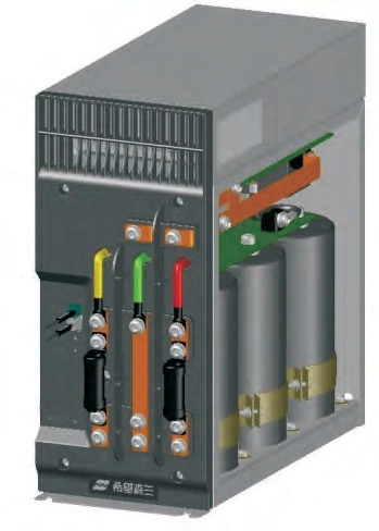
Accessories and configuration checklist
| Option / accessory | Engineering purpose |
|---|---|
| Encoder interface | SL-PG-3 option for supported encoder signals, including differential and push-pull interfaces; confirm signal level, supply and pulse frequency. |
| Communication modules | PROFIBUS DP or TCP/IP integration when required by the plant controller; confirm the exact protocol and data mapping. |
| Bypass and isolation cabinets | Select manual/automatic bypass, switching sequence, isolation and interlocking to suit operating continuity. |
| Current-limiting equipment | Included where required by the selected rating and system design; account for its additional footprint. |
| Air or water cooling | Specify room heat rejection, ventilation or cooling-water conditions, access and maintenance requirements. |
| Enclosure upgrades | IP42 option or custom IP54 enclosure. Cooling and installation conditions remain part of the engineering review. |
| Spare parts and service package | Define spare power cells, fans, boards, commissioning support and operating-team training in the project scope. |
Electrical capability with clear selection limits.
The cascaded multilevel architecture and phase-shifting transformer are designed to produce a near-sinusoidal output and reduce input harmonics. The following performance values support application selection.
| Performance item | Published value | Selection note |
|---|---|---|
| Inverter efficiency | 98.5% | Inverter efficiency; excludes the phase-shifting transformer. |
| Power factor | ≥ 0.96 | Confirm the design operating point and network conditions. |
| Harmonic performance | THD ≤ 4% at 3–4.16 kV; ≤ 2% at 6–13.8 kV | Confirm the measurement point, loading, network impedance and project harmonic limits. |
| Overload capability | 120% for 120 s; 150% for 5 s | Select against the complete motor load cycle and cooling conditions. |
| High-current protection | 200%: immediate protection | This is a protection threshold, not a continuous or timed overload rating. |
| Frequency resolution | 0.01 Hz | Digital setpoint resolution; not a stated motor-speed accuracy. |
| Acceleration / deceleration | 0.1–3,600 s | Set according to motor, inertia, load and permitted process ramps. |
| Output frequency | 0–120 Hz | The permitted motor and driven-equipment speed range governs the final setting. |
Production validation includes functional checks, aging, withstand-voltage testing and load-testing arrangements. Agree the required factory acceptance test, acceptance criteria and project documentation before manufacture.
Plan the electrical room, environment and service access.
| Item | Specification / project requirement |
|---|---|
| Rated input | 3–13.8 kV, ±10%; 50/60 Hz, ±5%, according to the selected configuration. |
| Full-load voltage variation | −20% to +15%. Lower-voltage operation requires derating and project review. |
| Operating temperature | −10 to +40 °C. Higher temperatures require a confirmed cooling and derating plan. |
| Operating humidity | Use 20–90% RH, non-condensing, as the conservative installation basis; confirm higher-humidity configurations. |
| Altitude | Provide the actual site elevation. Sites above 1,000 m require a configuration-specific insulation, cooling and derating review. |
| Storage | −40 to +70 °C; dry, protected storage without condensation, rain or outdoor exposure. Follow periodic inspection requirements in the manual. |
| Cooling / enclosure | Forced air or water cooling. IP31 standard, IP42 optional, custom IP54 available. |
| Installation environment | Indoors, without explosive/corrosive gases, conductive dust or oil mist. Keep air passages clear and separate MV power cables from low-voltage control wiring. |
| Control supply | 220 V AC, 3 kVA, 50/60 Hz; optional DC supply by project arrangement. |
| Analog I/O | 3 inputs / 4 outputs; selectable voltage and current signals, including 0/4–20 mA and 0/2–10 V. |
| Digital I/O | 8 inputs / 5 outputs; output arrangement includes transistor and relay outputs. |
| Mechanical planning | Verify foundation, delivery openings, lifting, service clearance, top fans, bypass cabinets and cable entry against approved drawings. |
Evaluating an ABB or Perfect Harmony alternative.
MAX-MV can be evaluated alongside established medium-voltage drive families for new projects or as a retrofit candidate. Compare the specific motor and duty point, then check control interfaces, protection, cooling, footprint and service requirements.
| Selection point | INOMAX MAX-MV | ABB ACS580MV | Innomotics Perfect Harmony GH180 |
|---|---|---|---|
| Motor-voltage range | 3–13.8 kV series capability; 7 published classes at 3–11 kV | 3.3–11 kV | 2.3–11 kV |
| Published family power range | 160 kW–40 MW series capability; standard tables to 10 MW, depending on voltage | 300 kW–6.3 MW | 0.12–25 MW |
| Cooling | Forced air or water, project selected | Air cooled | Air cooled to 12 MW; water cooled to 25 MW |
| Power architecture | Phase-shifting transformer and cascaded modular cells | Integrated transformer and cascaded H-bridge cells | Integrated transformer and modular power cells |
| Retrofit assessment | Motor/current/duty matching, controls, bypass, installation and commissioning review | Assess the exact installed model and project configuration | Assess the exact installed model and project configuration |
A replacement is an engineering exercise, not an automatic drop-in interchange. Send the existing drive nameplate, motor data, drawings and operating requirements for a model-specific assessment. Efficiency values are not ranked here because published measurement boundaries differ.
Medium-voltage drives in real industrial applications.
Explore installed MAX-MV drives and project selections for petrochemical plants, industrial fans, MVR evaporation and process compressors. Read the application details here, then contact INOMAX for information relevant to your own project.
Rich-gas compressor · 10 kV · 4,000 kW
Jiangsu Jurong Chemical
A MAX-MV-100-4000 high-voltage drive was applied to rich-gas compressor variable-speed control at Jiangsu Jurong Chemical in 2015.
For a similar compressor package, discuss the permitted speed range, motor starting duty, compressor protection and DCS interfaces with our application team.
Incinerator induced-draft fans · 10 kV · 630 kW
Jinling Petrochemical
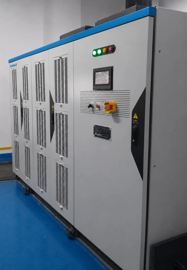
The installation used MAX-MV-100-630-C8601A and MAX-MV-100-630-C8601B drives for incinerator induced-draft fans, with on-site commissioning.
For comparable ventilation duties, review fan inertia, draft-control feedback, restart permissions and the process response to a drive trip.
Petrochemical production · MAX-MV drive installation
Hainan Yisheng Petrochemical
MAX-MV high-voltage drives are installed in the Hainan Yisheng petrochemical project. The project record reports stable drive operation.
Discuss your process duty, electrical-room layout and maintenance requirements to identify a suitable cabinet and support package.
Yili Chuanning Biotechnology · 10 kV, 8,000 kW
A MAX-MV-100-8000 drive was selected for the Xi’an Shaangu Power steam-compressor project serving Yili Chuanning Biotechnology’s secondary-settlement effluent treatment and MVR evaporation system. The project combines a 202 t/h vapour-compressor package with a 396 t/h MVR evaporation system.
For a similar MVR package, our application team can review the motor current, operating speed range, compressor control interfaces and drive cooling arrangement with the equipment supplier.
More project applications
Different projects can use the same drive model. Each row below identifies a separate application and its recorded equipment scope.
| Customer / end user | Application | Drive selection | Project scope |
|---|---|---|---|
| Yili Chuanning Biotechnology | Effluent-treatment MVR steam compressor | MAX-MV-100-8000 | Compressor package through Xi’an Shaangu Power; secondary-settlement effluent treatment and MVR evaporation. |
| Jiangsu Suyanjingshen | Screw-compressor retrofit | MAX-MV-060-3550 | 3,550 kW high-voltage inverter renovation project. |
| Jiangsu Suyanjingshen | Steam compressor | MAX-MV-060-7100 | Salt-production plant technical transformation for coal reduction and process supply. |
| Sichuan Hebang Biotechnology | Centrifugal steam compressors | MAX-MV-100-4000; MAX-MV-100-4500 | Wastewater resource-utilization and biochemical pretreatment project; two separate drive selections. |
| Hebei Xinhai Chemical | Reforming circulating-hydrogen compressor | MAX-MV-100-2500-T | 10 kV compressor-drive dual-redundancy reconstruction project. |
| Hebei Xinhai Chemical | Phase V catalytic-plant centrifugal compressor | MAX-MV-100-2500-T | Separate Phase V application with a dual-unit thermal-redundancy arrangement. |
| Hebei Xinhai Chemical | Phase V diesel-hydrogenation compressor | MAX-MV-100-2500-T | Circulating-hydrogen compressor with a 10 kV dual-unit thermal-redundancy system. |
| Sichuan Hongya Qingyijiang Sodium Sulphate | MVR compressor | MAX-MV-100-4500 | EGV90 compressor-unit inverter package through Xi’an Shaangu Power. |
| Jilin Quande Straw Comprehensive Utilization | Evaporation steam compressor | MAX-MV-100-3150 | Fertilizer-workshop evaporation compressor application. |
| Heilongjiang Quanlin Ecological Agriculture | Evaporation steam compressor | MAX-MV-100-5600 | Evaporation workshop of the Jiamusi project. |
| Shanxi Meijin Huasheng New Chemical Materials | Screw compressor | MAX-MV-100-4500 | Ethylene-glycol co-production LNG project. |
| Hejin Huayuan Gas | Screw compressor | MAX-MV-100-4000 | Coke-oven gas to LNG and synthetic-ammonia project. |
| Guangdong Huihong Technologies | Centrifugal compressor | MAX-MV-100-2000 | Rinsing-water desalination pretreatment for cement-kiln fly-ash co-processing. |
| Jiaokou County Tianma Energy Industry | Oxygen-generator compressor | MAX-MV-100-2500 | 6,000 m³ oxygen-generator unit project with undisturbed switching. |
Need more detail about a comparable project?
Email your application, motor voltage and power to info@inomaxtechnology.com. Our team can provide relevant project information, drawings, test documentation and configuration details after discussing your requirements.
Catalog and user manual.
MAX-MV catalog · V2610
Product architecture, functions, options, ratings, dimensions and application references.
MAX-MV user manual · V2610
Installation, operation, parameter settings, troubleshooting, communications and maintenance.
Project-specific documents
Project references, drawings, certificates and test reports are provided by our team according to your application.
Need a project drawing, communication map or factory acceptance test plan? Ask the application team for documents matched to your selected equipment.
Questions to resolve before specifying a medium-voltage drive.
Practical answers for distributors, EPC contractors, system integrators and equipment manufacturers evaluating MAX-MV. Explore selection, retrofit, availability, delivery and project support.
24 questions across 5 topics
Selection & project economics
How do I select a MAX-MV drive for a 3.3, 4.16, 6.6 or 10 kV motor?
Match motor voltage and rated current first, then verify the load cycle, overload, speed range and site derating. MAX-MV selection tables cover 3, 3.3, 4.16, 6, 6.6, 10 and 11 kV; power and current limits differ by voltage. For example, the 6.6 kV MAX-MV-066-2000 reference selection is 2,000 kW and 219 A. A motor with the same kW may need a different selection if its current or duty is higher.
Send a motor nameplate photo and explain what it drives. For 13.8 kV or a rating beyond the listed tables, request an engineered selection.
Should I use a medium-voltage VFD or a medium-voltage soft starter?
Choose a medium-voltage VFD when the process needs continuous speed control, such as varying pump flow, fan airflow or compressor capacity. A soft starter is suitable when the main need is controlled starting and the motor subsequently runs at line frequency. MAX-MV can also be configured for variable-frequency starting followed by synchronized transfer, but that is a different system from continuous variable-speed operation.
Describe the required running speed, starting torque, starts per hour and whether more than one motor must be started. These determine which arrangement is worth evaluating.
How much energy can an MV drive save on a pump or fan, and how do we calculate payback?
Savings depend on the actual operating profile and existing control method. A pump using a throttling valve or a fan using a damper can be a good candidate when demand regularly falls below full output. A high static head, a process that always needs full speed, or minimum-flow constraints can reduce the opportunity. No fixed energy-saving percentage applies to every installation.
Use measured input kW, operating hours, flow or pressure requirements and the electricity tariff. Compare annual energy cost before and after the change, including transformer, drive and cooling losses, against the complete installed investment.
What must a compressor OEM check before specifying a medium-voltage VFD?
Confirm the compressor type, permissible speed range, torque and inertia, acceleration time, lubrication requirements and process protection. Centrifugal compressors also need coordination with the compressor supplier’s surge-control strategy; an MV drive does not replace anti-surge protection. MAX-MV supports induction, synchronous and permanent-magnet motors in appropriately selected configurations.
For an MVR or process-compressor package, share the compressor map or operating envelope and the motor data. Relevant MAX-MV experience includes rich-gas compression and an 8 MW MVR steam-compressor project.
What should be included when comparing medium-voltage VFD prices?
Compare the complete installed scope at the same motor rating and duty. A MAX-MV system brings together a phase-shifting transformer, cascaded power cells and control equipment. Bypass, isolation, current limiting, cooling, enclosure upgrades and spares depend on the selected configuration. Upstream switchgear, site cabling, civil works, freight and commissioning responsibilities should be identified separately.
Ask for an itemized quotation showing supply boundaries, exclusions, drawings, tests, service scope and warranty terms. This makes an EPC bid or a comparison with another supplier meaningful.
Retrofit & electrical integration
Can MAX-MV replace an ABB ACS580MV or Siemens / Innomotics Perfect Harmony drive?
MAX-MV can be evaluated for a replacement project when its electrical rating, motor control and operating duty match the installation. The review covers the existing transformer and switchgear arrangement, motor and cables, PLC/DCS interfaces, protection, cooling, cabinet footprint and shutdown window. Matching kW alone does not establish interchangeability.
Send the existing drive and motor nameplates, single-line diagram, cabinet dimensions and the reason for replacement. Agree which equipment can remain and what must change before committing to an outage schedule.
Can I keep the existing medium-voltage motor and long motor cables?
Existing motors and cables may be retained after an engineering assessment. MAX-MV uses a cascaded multilevel output with a near-sinusoidal waveform, but motor condition, insulation, cable construction and length, grounding and the required speed range still matter. Low-speed motor cooling and driven-equipment limits also need to be checked.
Provide the motor datasheet or test records and the installed cable type, length and route. Confirm any required output filtering or motor measures for that exact installation; there is no universal cable-length approval for every MAX-MV configuration.
Can an 11 kV supply feed a 10 kV motor through MAX-MV?
A project with different supply and motor voltages requires a specifically engineered transformer and drive arrangement. State both voltages separately, together with frequency and the motor current. Transformer winding selection, insulation, protection and the available output voltage must be checked for the proposed combination.
Line bypass needs particular attention: a 10 kV motor cannot simply be connected to an 11 kV bus because a VFD is installed. The approved bypass arrangement must respect the motor’s supply limits.
Will MAX-MV meet the project’s IEEE 519 or utility harmonic limits?
Compliance must be assessed for the project’s defined point of common coupling and operating conditions. MAX-MV’s phase-shifting transformer and multi-pulse cell inputs reduce supply harmonics. A drive-level THD value alone does not establish compliance for the complete plant; network strength, other nonlinear loads and operating load all affect the result.
Send the single-line diagram, supply transformer data, available short-circuit level and the required limits. Agree voltage distortion, current distortion/TDD, the measurement point and the acceptance method in the technical specification.
Can MAX-MV run on a generator or a weak grid with voltage dips?
Generator-fed and weak-grid applications require a power-system review. Transformer energization, generator capacity and controls, other connected loads, voltage dips and the motor’s acceleration demand must be considered together. MAX-MV includes grid-disturbance and restart functions, with performance depending on the load and selected settings.
Distinguish riding through a disturbance from restarting after supply recovery. Specify the disturbance duration and the process’s acceptable speed or torque interruption; confirm any input current-limiting equipment and recovery sequence for the project.
Availability, cooling & controls
If a power cell fails, can production continue at full speed?
Configured MAX-MV cell bypass can isolate an affected power cell and support continued operation. Full speed and full load are not automatic: the remaining output voltage, bypass strategy, available cell margin and motor demand determine what can be sustained. This matters especially for critical fans, pumps and compressors.
State the minimum acceptable output after a cell fault. Define the required bypass arrangement, reduced-output duty and spare-cell plan before ordering.
For a 24/7 process, should I specify line bypass, a standby drive or redundant control?
These arrangements address different failure modes. Line bypass lets a suitable motor run at fixed line frequency and requires compatible process, grid and motor conditions. A standby drive preserves a variable-speed route, while controller redundancy addresses control availability. MAX-MV offers project-selected bypass and redundancy arrangements.
Start with the maximum permitted process interruption and whether fixed-speed operation is acceptable. Define transfer interlocks, switching sequence and acceptance tests; an automatic bypass label alone does not guarantee uninterrupted process operation.
Should we choose air cooling or water cooling for a hot, dusty site?
Choose cooling around the installation’s heat-removal capacity, cleanliness, available utilities and maintenance resources. Air-cooled MAX-MV systems require adequate clean airflow and room heat removal. Water-cooled configurations require a defined cooling-water supply, water quality and heat-rejection arrangement. IP31 is standard, IP42 is optional and a customized IP54 enclosure can be specified.
Provide maximum room temperature, altitude, dust conditions and available cooling water. Confirm derating and enclosure design together; IP54 alone does not make a cabinet suitable for every outdoor or corrosive environment.
Will the cabinet fit our electrical room, and how much cooling capacity is needed?
Use the approved arrangement drawing and loss data for the selected rating. Check transport sections, door openings, floor loading, cable entry, top fans, bypass or current-limiting cabinets and maintenance clearance. A catalog cabinet size does not include every project option. Room cooling must account for both drive and transformer heat released into the room.
Send a room plan and delivery-access dimensions early. The 98.5% inverter-efficiency figure is not the efficiency of the complete transformer-plus-drive installation, so it should not be used alone to size room cooling.
Can MAX-MV integrate with our PLC or DCS, and what happens if communication is lost?
MAX-MV supports hardwired control and monitoring, with Modbus RTU over RS485 and project-selected communication options such as PROFIBUS DP. Confirm the exact protocol and module when TCP/IP integration is requested. Speed reference, run/stop, ready, alarm, fault and operating values should be mapped with the control-system supplier.
Agree local/remote priority, communication-loss behaviour, restart permissions, emergency-stop interfaces and bypass feedback in the control philosophy. Include these signals and failure responses in commissioning tests.
Project evidence, delivery & service
Does INOMAX have medium-voltage drive references comparable to our project?
MAX-MV project experience includes a 10 kV, 4,000 kW rich-gas compressor at Jiangsu Jurong Chemical, 10 kV, 630 kW incinerator induced-draft fan drives at Jinling Petrochemical, and a 10 kV, 8,000 kW MVR steam-compressor project for Yili Chuanning Biotechnology.
Select a reference by load type, voltage, power and control requirements. For an EPC or OEM evaluation, ask to discuss the closest configuration and its supply scope rather than assuming a different plant’s operating result applies to your project.
What technical documents are needed for an EPC tender or consultant approval?
Define a project submittal package covering the selected rating, compliance/deviation list, single-line diagram, cabinet arrangement, terminal drawings, control interfaces, cooling requirements, inspection plan and spare-parts scope. Identify the applicable product standards and any mandatory third-party certification at the enquiry stage.
Request certificates and test reports applicable to the offered equipment and scope. A company quality-system certificate or a certificate for another product is not a substitute for a required MV-drive approval.
What will be checked at factory acceptance testing, and can our team witness it?
MAX-MV manufacturing verification includes insulation/withstand-voltage checks, functional tests, aging and complete-system load-testing arrangements. For your order, agree a written factory acceptance test (FAT) plan that identifies the exact rating, test setup, loading, duration and pass/fail criteria. Include protection, interfaces and configured bypass functions where applicable.
Request in-person, remote or third-party witnessing when placing the order so the scope and schedule can be agreed. Establish which performance checks are completed at the factory and which require site acceptance testing with the actual motor and process.
What determines the production lead time, and can delivery match our shutdown?
The delivery schedule depends on the transformer and power rating, enclosure, cooling, bypass configuration, document approval and required testing. For a planned retrofit, the useful commitment is a schedule tied to design approval, manufacturing completion, FAT, shipment and site commissioning readiness.
Send the required on-site date and shutdown window with the enquiry. Ask for the latest drawing-approval date and a confirmed dispatch plan, including transport time and any customer-supplied equipment. Lead time is confirmed for the agreed project configuration.
What warranty applies to MAX-MV, and who handles overseas commissioning?
The MAX-MV quotation and contract define the warranty duration, its commencement date and the agreed service responsibilities. Overseas projects should identify who performs installation checks, first energization, motor tuning, process testing and operator handover before shipment.
Ask for written coverage of parts, labour, travel and freight, response arrangements, exclusions and any commissioning prerequisites. For an EPC or distributor-supplied installation, agree the responsibilities of INOMAX, the local partner and the end user in the same service plan.
Which spare parts and maintenance support should we plan for a remote site?
Build the spares package around the installed configuration and the cost of downtime. Candidates include a matching power cell, selected control/interface boards, cooling fans, fuses and filters. Confirm compatibility and the required quantities rather than assuming one spare fits all voltage and current ratings.
Agree parts lead times, local stock responsibility, maintenance training and fault-escalation contacts. Keep the serial number, parameter backup and fault logs available; service or replacement of medium-voltage equipment requires trained personnel and the approved isolation procedure.
OEM, EPC & distributor cooperation
Can MAX-MV be supplied as part of our pump, fan or compressor OEM package?
MAX-MV can be evaluated as the motor-control element of an OEM equipment package. Define the motor, load curve, speed range, footprint, cooling and interface requirements together. For repeat equipment builds, an agreed configuration and document set help keep quotations, integration and servicing consistent.
Specify who supplies the motor, switchgear, cooling auxiliaries and process controls. Discuss branding, language, testing and repeat-order requirements with INOMAX so the quotation identifies the actual customization and supply scope.
How can a local distributor or system integrator work with INOMAX on MV projects?
A useful partnership starts with the applications and projects you serve: pump stations, industrial fans, compressors, plant expansion or drive replacement. Discuss technical selection, tender support, customer training, commissioning responsibilities and a local spare-parts plan alongside commercial terms.
Share your market, engineering/service capability and current project pipeline. Project pricing, branding, territory arrangements and support commitments are agreed for the partnership; they should be confirmed before being promised to an end customer.
What is the quickest way to obtain a useful MAX-MV technical proposal?
Start with a motor nameplate photo, the driven equipment, supply voltage, project country and required delivery date. If you are replacing an existing drive, add its nameplate and the main problem you want to solve. These details are enough to begin the selection discussion.
For a firm offer, the team will then review load and overload, speed range, site conditions, bypass, control interfaces and the required documents/tests. An EPC specification or OEM equipment datasheet is helpful if already available.
No matching question. Try a shorter term, or send your application question to INOMAX.
Let’s define your medium-voltage drive.
For your next project
Share your motor data and application. Our team can help define the rating, cabinet arrangement, options and technical documentation for your inquiry.
Email: info@inomaxtechnology.com
For distributors & integrators
Discuss local-market cooperation, application engineering, product training, spare-parts planning and project support with INOMAX.


