
← MAX-MV series overview · Explore all 10 selection guides
01 · Product overview
High-power control built around the electrical system.
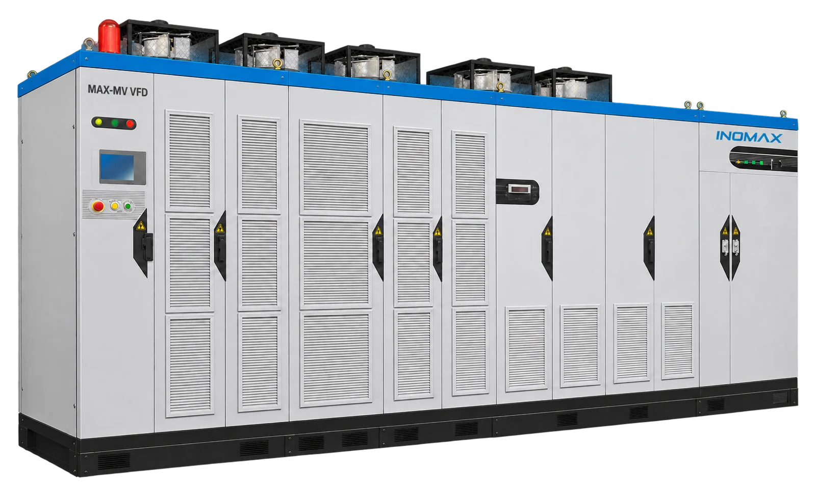
MAX-MV combines a phase-shifting transformer, cascaded power cells and coordinated digital control for large medium-voltage motors. The 10 kV and 11 kV selection ranges extend from 200 to 10,000 kW, with voltage-specific current ratings and cabinet arrangements.
The wider series supports engineered configurations up to 13.8 kV. For that voltage, the motor data, incoming network, insulation coordination, cooling and acceptance requirements are reviewed before an ordering code and final arrangement are issued. The 10 or 11 kV model list should not be reused as a 13.8 kV ordering table.
02 · Rating and cabinet selection
Power, voltage and current selection
Match the motor nameplate current, overload duty and site derating before confirming a model. The filters below help you compare the listed selections; final cabinet and option details are agreed for the project.
68 reference selections
No matching selection in this table. Send your motor data for engineering review.
Dimensions exclude top fans, bypass additions and service clearances. At 6.6 kV from 2,800 kW and 11 kV from 4,500 kW, add an 800 mm current-limiting cabinet with matching depth and height. Use the approved project drawing for the complete installation.
13.8 kV configurations are engineered to the project. Confirm the ordering code for the 11 kV, 10 MW selection before purchase.
03 · Application fit
Application requirements that shape the package
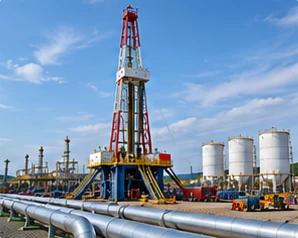
Petrochemical and LNG processes
Process compressors, circulating hydrogen duties, feedwater pumps and utility fans. Define continuity and hazardous-area separation requirements.
MVR and large compressors
Multi-megawatt steam-compressor systems. Coordinate speed range, motor technology, process protection and the equipment manufacturer’s limits.
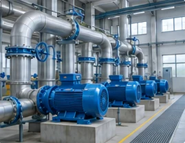
Large industrial infrastructure
Power, metals, water and manufacturing utilities where the motor voltage, protection system and shutdown plan govern the drive package.
04 · Integration and options
Functions, accessories and engineering decisions
Coordinate supply voltage and motor voltage
A site can have different incoming and motor nameplate voltages, but the transformer and output arrangement must be engineered accordingly. Direct-line bypass requires a separate voltage compatibility check. An 11 kV incoming supply must not simply be switched onto a 10 kV motor.
Define insulation and upstream protection
Provide the single-line diagram, earthing arrangement, short-circuit information and switchgear interface requirements. Confirm protection settings, cable terminations and the applicable project standards with the plant electrical engineer.
Reserve space for the full configuration
At 11 kV, selections from 4,500 kW inclusive need an additional 800 mm current-limiting cabinet. Include top fans, bypass equipment, maintenance clearances and transport sections in the room and foundation design.
Make the acceptance criteria measurable
Agree the required voltage, current, load-test arrangement, control sequences, protective functions, interface checks and document package. Harmonic limits should identify the measurement point and network conditions. Witness testing and shipping release belong in the project schedule.
Define the equipment scope
| Configuration item | What to agree |
|---|---|
| Motor control and feedback | Motor technology, control mode and encoder interface where required |
| Bypass / isolation | Manual or automatic line bypass, isolation and switching interlocks; selected for the process |
| Control integration | Standard Modbus RTU / I/O; optional PROFIBUS DP or exact TCP/IP arrangement |
| Continuity options | Cell-bypass strategy, controller redundancy or standby drive as project-selected |
| Service package | Spare cells, fans, boards, commissioning and training scope |
05 · Electrical performance
Performance for a defined operating duty
| Performance item | Selection basis |
|---|---|
| Motor-control modes | V/F; V/F with feedback; sensorless vector; closed-loop vector |
| Overload capability | 120% for 120 s; 150% for 5 s, checked against selected configuration and duty |
| Frequency resolution | 0.01 Hz; resolution is distinct from motor-speed accuracy |
| Acceleration / deceleration | 0.1–3,600 s; set within motor and process limits |
| Inverter efficiency | 98.5%; excludes the phase-shifting transformer |
| Power factor | ≥0.96 at the specified operating conditions |
| Harmonic performance | THD ≤4% for 3–4.16 kV; ≤2% for 6–13.8 kV. Confirm measurement point, loading and network conditions. |
Confirm performance at the required motor duty, supply conditions and cooling arrangement. For regenerative or braking loads, specify the operating cycle so a suitable two- or four-quadrant power stage can be selected.
06 · Technical data
Installation, environment and maintenance
| Item | Requirement / configuration |
|---|---|
| Operating temperature | −10 to +40°C; higher temperature requires an approved cooling and derating plan |
| Humidity | 20–90% RH, non-condensing, as the installation basis; confirm higher-humidity configurations |
| Altitude | Provide the site elevation; above 1,000 m, review insulation, cooling and derating for the selected configuration |
| Storage | −40 to +70°C; dry, protected storage without condensation or outdoor exposure |
| Cooling and enclosure | Forced air or water cooling; IP31 standard, IP42 optional, custom IP54 |
| Control supply | 220 V AC, 3 kVA, 50/60 Hz; optional DC supply by project arrangement |
| Control interfaces | 3 analog inputs / 4 analog outputs; 8 digital inputs / 5 digital outputs; RS485 / Modbus RTU standard |
| Installation | Indoor electrical room; no explosive/corrosive gases, conductive dust or oil mist; keep cooling and service access clear |
Plan safe service access, delivery openings, foundation loading and separate power/control cable routes. Inspection intervals and replacement work follow the installed equipment manual and the site maintenance plan.
07 · Supplier and configuration comparison
Compare complete proposals on the same basis
| Comparison point | What to check |
|---|---|
| Voltage and insulation | Match the exact supply/motor combination and site insulation requirements. |
| Power and overload | Compare continuous current and the same operating cycle, rather than family maximum MW. |
| Heat and footprint | Use complete package losses and the final general-arrangement drawing. |
| Acceptance and lifecycle | Compare FAT scope, commissioning responsibilities, spare modules and service terms. |
Ask each supplier to identify inclusions, exclusions and deviations. The selected rating, options, installation work, acceptance test and service responsibilities should be clear before comparing the final price.
08 · Customer applications
Relevant industrial project experience
Jiangsu Jurong Chemical
10 kV · 4,000 kW
MAX-MV-100-4000 was applied to rich-gas compressor variable-speed control in 2015. The application illustrates coordination of a large motor drive with an industrial process.
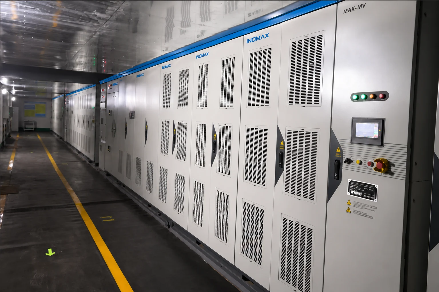
Discuss a comparable configuration with INOMAX. The motor, equipment scope and operating conditions are assessed separately for each project.
Practical project FAQ
Questions to resolve before ordering
6 questions
Is 13.8 kV available as a standard stock model?
13.8 kV is part of the series engineering capability. A project-specific review is required to confirm the rating, power stage, transformer, cooling and cabinet arrangement. Request a technical proposal rather than selecting an unconfirmed standard model code.
Can an 11 kV supply drive a 10 kV motor?
It can be evaluated with a transformer and drive arrangement designed for both voltages. The complete circuit, insulation and output operating point must be checked. If line bypass is required, its voltage conversion and switching arrangement need their own design review.
How do 10 kV and 11 kV 4 MW selections compare?
The 10 kV MAX-MV-100-4000 reference is 290 A with a 4700 × 1300 × 2200 mm base cabinet. The 11 kV MAX-MV-110-4000 reference is 262 A with a 5300 × 1500 × 2200 mm base cabinet. Motor current and site conditions govern the final selection.
Can I order a 10 MW, 11 kV drive from this table?
The 11 kV range includes a 10,000 kW, 656 A selection. Obtain the confirmed 11 kV ordering code and project drawing from INOMAX before placing an order. Cooling, bypass and current-limiting equipment must be included in that confirmation.
Does the drive meet our utility harmonic specification?
The project requires a network-specific assessment. State the point of common coupling, supply impedance, other nonlinear loads and the required voltage/current distortion limits. A family THD figure alone is not a guarantee for every plant connection.
Can we specify a synchronous or permanent-magnet motor?
Yes, these motor technologies have dedicated configurations. Provide excitation or magnet data as applicable, rated current, speed range, feedback requirements and starting duty so the motor-control arrangement and suffix combination can be confirmed.
No matching question. Ask our application team.
Technical resources
Catalog, manual & project support
MAX-MV catalog
Ratings, dimensions, features and configuration options.
MAX-MV user manual
Installation, operation, control settings and maintenance.
Project-specific documents
Contact INOMAX for project records, drawings, certificates and test reports matched to your application.
09 · Start the conversation
Let’s define your next MAX-MV project.
Request a High-Voltage Configuration
Send the supply and motor ratings, single-line diagram, site conditions and acceptance requirements for a configuration review.
Email: info@inomaxtechnology.com
Build your local MAX-MV business
Discuss the industries you serve, application-engineering support, training, commissioning and spare-parts planning. Commercial and service arrangements are defined for your market and projects.


