

ACS890 / Regenerative AFE
Regeneration starts with the machine’s energy cycle
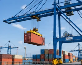
Return usable braking energy through an engineered active front end. ACS890 ALM / AFE modules regulate the DC link and control grid current as part of a coordinated drive system.
When the driven load returns energy, the motor-side inverter can feed it into the DC link. An appropriately configured ALM / AFE stage can transfer that energy toward the AC supply. The AFE is the grid-side converter; the motor still requires the suitable INV / SMM motor-control stage.
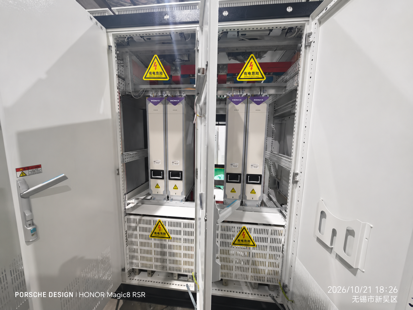
The regenerative front end is not an isolated module choice. The catalog configuration combines the control unit, active front end, matched SLC filter, CHG precharge and VSM grid feedback. Protection, grid measurements, DC-link operating range and the site supply conditions must be coordinated.
Specify maximum and sustained returned power, the braking repetition rate and whether other DC-bus branches consume energy during the same cycle. A common DC bus can share energy between loads, but the front end and any braking-resistor path must still handle the remaining system-level energy balance.
Active control of grid current provides a basis for low-harmonic engineering. A numerical harmonic guarantee should identify the selected filter, supply conditions, load range and measurement point; it should not be inferred from the term AFE alone.
DC-link regulation
Catalog functions include DC-voltage regulation, voltage boost / buck and constant-voltage / constant-power modes in the applicable power-conversion configuration.
Matched grid interface
Treat the ALM, SLC, CHG and VSM arrangement as one coordinated grid-side design.
Duty-based power sizing
The motor-side inverter and grid-side AFE can see different peak and continuous duties. Select each from its actual current and energy profile.
System configuration
Define the power path and supporting equipment.
Functional configuration guide, not an installation wiring diagram. Final protection, connections and component compatibility follow the engineered system documentation.
Selection data
Representative ACS890 AFE module entries
| Model | Class / cooling | PN (kW) | Continuous current | LD kW / A | HD kW / A | W × D × H (mm) / weight |
|---|---|---|---|---|---|---|
| ACS890-T771-0205-11 | 1140 V AC / Liquid | 400 | 205 / 200 IAC / IDC (A) | 388 / 194 | 300 / 150 | 170×510×930 / 51.0 kg |
| ACS890-T981-0921-11 | 1140 V AC / Liquid | 1800 | 921 / 900 IAC / IDC (A) | 1746 / 873 | 1350 / 675 | 240×630×1260 / 130.0 kg |
| ACS890-R411-0034-4 | 400 V AC / Air | 22 | 34 / 37 IAC / IDC (A) | 21 / 36 | 17 / 28 | 86×230×290 / 3.1 kg |
| ACS890-R841-0859-4 | 400 V AC / Air | 560 | 859 / 933 IAC / IDC (A) | 543 / 905 | 420 / 700 | 170×585×980 / 73.0 kg |
| ACS890-L701-0691-4 | 400 V AC / Liquid | 450 | 691 / 750 IAC / IDC (A) | 437 / 728 | 338 / 563 | 170×510×930 / 55.0 kg |
| ACS890-L721-0859-4 | 400 V AC / Liquid | 560 | 859 / 933 IAC / IDC (A) | 543 / 905 | 420 / 700 | 170×510×930 / 55.0 kg |
| ACS890-R661-0135-7 | 700 V AC / Air | 160 | 135 / 160 IAC / IDC (A) | 155 / 155 | 120 / 120 | 125×380×635 / 20.0 kg |
| ACS890-R891-0532-7 | 700 V AC / Air | 630 | 532 / 630 IAC / IDC (A) | 611 / 611 | 473 / 473 | 170×585×980 / 76.0 kg |
| ACS890-L751-0473-7 | 700 V AC / Liquid | 560 | 473 / 560 IAC / IDC (A) | 543 / 543 | 420 / 420 | 170×510×930 / 55.0 kg |
| ACS890-T931-1268-7 | 700 V AC / Liquid | 1500 | 1268 / 1250 IAC / IDC (A) | 1455 / 1213 | 1125 / 938 | 240×630×1260 / 130.0 kg |
Read the current correctly: inverter values are motor IN; AFE values are AC / DC currents. LD and HD cells show the catalog power / current references. Continuous ratings use the catalog conditions; where specified, LD is 110% for 1 minute in 5 and HD is 150% for 1 minute in 5. Apply ambient, installation and topology-specific derating. Dimensions are for modules, not complete cabinets.
Accessories & integration
Specify the complete system package.
| Component / option | Role and selection requirement |
|---|---|
| SLC grid filter | Matched filter for the selected ALM / AFE voltage, current and topology. |
| CHG10 / CHG20 / CHG30 | Active precharge family selected for the system voltage and DC-link requirements. |
| EX-VSM-01 | AC grid-status detection module with application-specific current measurement and scaling. |
| CU200 / CU200-PN / CU200-EC | Control and the required PLC communications interface. |
| CA04-SF5 cables | Catalog shielded CAT5 FLYLINK cable options for synchronized module communication. |
| INV / SMM motor stage | Required for controlled motor operation; the AFE is not a direct motor-drive substitute. |
| BRK + resistor, where specified | Dynamic braking path selected from resistance, returned energy and thermal duty. Direct BRK paralleling is prohibited. |
| Surge protection / auxiliary supply / I/O | Components matched to the grid, DC-link, interlock and cabinet design. |
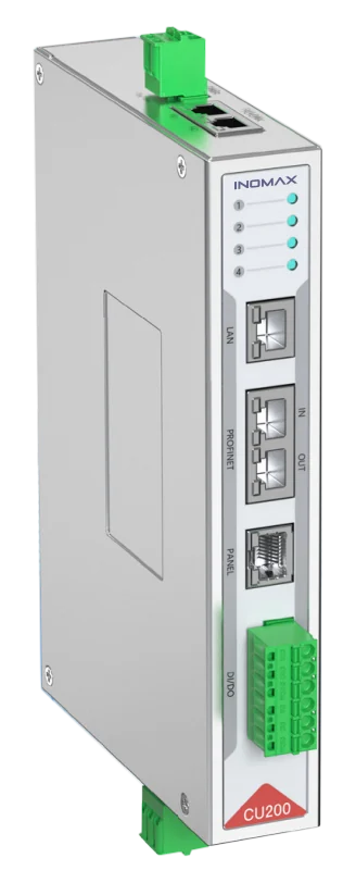
Control, feedback and power must match.
Include the PLC interface, encoder, operator panel, auxiliary supply, precharge and installation hardware in the quotation. Availability and compatibility depend on the selected module and cabinet configuration.
Application engineering
Match the configuration to the duty.
Dynamometers and test benches
Coordinate motoring and generating cycles, feedback requirements and returned power.
Hoists, winches and descending loads
Assess the repeated energy return and braking strategy alongside the machine’s mechanical and safety design.
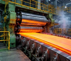
Steel rolling and coordinated process lines
Share energy across the DC link where appropriate and size the grid-side stage for the net energy exchange.
Product FAQ
Questions about regenerative afe.
What does an ACS890 AFE do?
The ALM / AFE regulates the DC link and controls current at the grid interface. In a suitable regenerative configuration it allows energy returned to the DC link to flow toward the AC supply.
Can the AFE connect directly to a motor?
No. The AFE is the grid-side conversion stage. A motor-drive system also needs the appropriate motor-side INV / SMM, control and feedback arrangement.
Which components are required around the AFE?
The catalog configuration is CU + ALM + SLC + CHG + VSM. The final protection, contactors, cabling and cabinet interfaces depend on the selected voltage, current and site requirements.
Does every ACS890 drive regenerate to the grid?
No. Grid regeneration depends on the selected front end and complete configuration. A basic rectifier, an active front end and a braking-resistor arrangement have different energy-flow capabilities.
Is a fixed THDi value guaranteed for all loads?
A harmonic-performance commitment must define the configuration and operating conditions. Provide the grid data, required limit and measurement point so INOMAX can assess the matched AFE/filter design.
Will regeneration eliminate the braking resistor?
That depends on the load cycle, supply availability, protection strategy and system requirements. The engineer should determine whether a resistor path is needed and rate it for the actual energy and thermal duty.
Can the AFE supply multiple motor inverters?
A suitable AFE can be part of an engineered common DC bus architecture. Size it against the combined motoring and generating duty of the branches, rather than only adding their nameplate kW.
What should I send for a regenerative-drive quotation?
Provide supply voltage and grid conditions, motor data, peak and sustained returned power, braking cycle, motor count, cooling and PLC requirements. The confirmed configuration determines production timing; the standard warranty is two years under the order terms.
Engineering enquiry
Request the right configuration.
Supply/grid data; motor ratings; peak and continuous regenerative power; load cycle; shared DC loads; harmonic requirement; cooling and PLC.
info@inomaxtechnology.com
Talk to INOMAX on WhatsApp →
Include your company and the page topic in the message. Manuals, drawings and certificates are supplied for the selected configuration.