

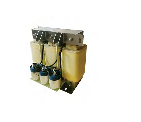
INOMAX · VFD Accessories
Near-sinusoidal motor supply · 400 V / 690 V · SLB
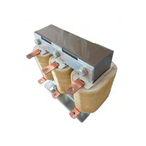
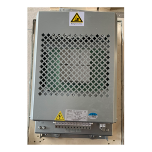
INOMAX SLB sine-wave filters are installed at the output of a VFD feeding an induction motor. They suppress and absorb higher-order harmonics from switching-frequency ripple to restore a near-sinusoidal output waveform. The result is reduced motor eddy-current losses and noise, insulation protection and support for substantially longer motor cables.
Power, voltage and current range
| Configuration | Power reference kW | Rated current A | Models |
|---|---|---|---|
| 400 V · SLB · sine-wave output filtering | 2.2–630 | 5–1200 | 23 |
| 690 V · SLB · sine-wave output filtering | 3.7–1000 | 5–1100 | 18 |
Choose the applicable configuration below. Voltage, current and power ranges vary by series and are not interchangeable across all models.
Application and connection
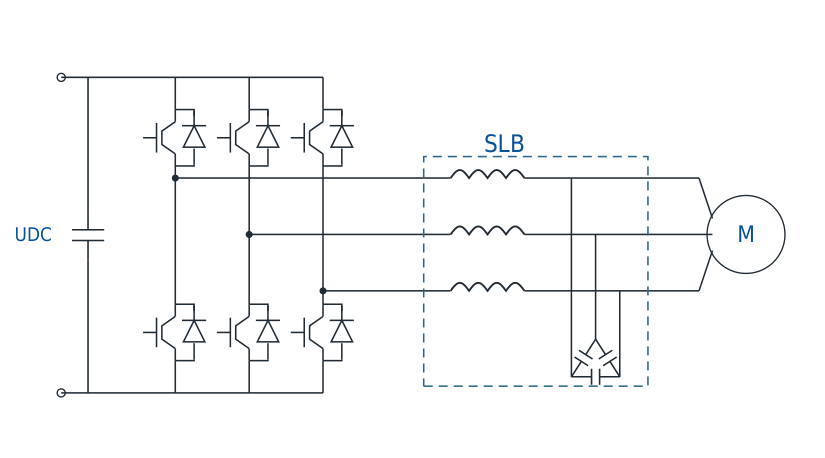
Near-sinusoidal waveform
Filter the VFD output waveform to reduce switching-frequency harmonic content at the motor.
Reduce motor noise and losses
Reduce the eddy-current losses and noise associated with higher-order PWM harmonics.
Support longer motor cables
Use output waveform filtering where the motor is installed far from the drive; confirm the permissible cable length for the selected system.
Match the switching frequency
The selection tables specify a minimum VFD switching frequency. This requirement is different from the maximum limits shown for output reactors and dV/dt filters.
Technical specifications
| Parameter | Specification |
|---|---|
| Rated voltage / frequency | 3-phase AC 400 V / 690 V; 50 Hz |
| Specified THDv / THDi | ≤5% for the listed voltage configurations; verify under the selected operating conditions |
| Insulation class | F / H |
| Noise level | ≤75 dB |
| Dielectric strength | AC 3000 V / AC 4200 V, 50 Hz, 5 s; leakage ≤5 mA; remove capacitors for the phase-to-phase test |
| Ambient temperature | −25°C to +55°C |
| Referenced standards | GB/T 1094.6-2011; IEC 289:1987; GB/T 19212.1-2023 |
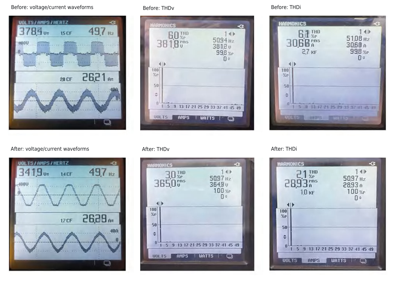
Before-and-after waveform tests
The test images compare voltage and current waveforms, voltage THD and current THD before and after sine-wave filtering. Use these to understand the filtering action; request model-specific verification for the intended drive and load.
Model selection and installation data
Select by motor current, system voltage, output frequency and the minimum VFD switching frequency. Confirm drive compatibility and motor-cable conditions. The 690 V 800 A, 1000 A and 1100 A models use separately arranged capacitors.
41 model ratings shown
Expand a configuration to compare models. On a phone, swipe the table horizontally to see all dimensions.
400 V · SLB · sine-wave output filtering · 23 models
| Model | Figure | Switching ≥ kHz | Drive kW | Rated A | Weight kg | W mm | D mm | H mm | W0 mm | D0 mm | A×B mm |
|---|---|---|---|---|---|---|---|---|---|---|---|
| SLB-0005-EISC | A-1 | 5 | 2.2 | 5 | 5.1 | 150 | 140 | 190 | 60 | 67 | 7×11 |
| SLB-0010-EISC | A-1 | 5 | 3.7 | 10 | 6.1 | 180 | 155 | 220 | 80 | 67 | 7×11 |
| SLB-0013-EISC | A-1 | 5 | 5.5 | 13 | 8.8 | 180 | 175 | 220 | 80 | 87 | 7×11 |
| SLB-0016-EISC | A-1 | 5 | 7.5 | 16 | 9.0 | 180 | 175 | 220 | 80 | 87 | 7×11 |
| SLB-0025-EISC | A-2 | 4 | 11 | 25 | 13.5 | 230 | 160 | 220 | 110 | 85 | 9×18 |
| SLB-0030-EISC | A-2 | 4 | 15 | 30 | 13.8 | 230 | 160 | 220 | 110 | 85 | 9×18 |
| SLB-0040-EISC | A-2 | 4 | 18.5 | 40 | 16.5 | 230 | 165 | 265 | 110 | 85 | 9×18 |
| SLB-0045-EISC | A-2 | 4 | 22 | 45 | 19.3 | 230 | 175 | 265 | 110 | 95 | 9×18 |
| SLB-0060-EISA | B | 3 | 30 | 60 | 27.7 | 260 | 225 | 285 | 140 | 110 | 9×18 |
| SLB-0075-EISA | B | 3 | 37 | 75 | 33.8 | 300 | 225 | 295 | 170 | 110 | 11×18 |
| SLB-0090-EISA | B | 3 | 45 | 90 | 35.7 | 300 | 230 | 295 | 170 | 110 | 11×18 |
| SLB-0110-EISA | C | 3 | 55 | 110 | 58.5 | 360 | 295 | 380 | 190 | 125 | 13×26 |
| SLB-0150-EISA | C | 3 | 75 | 150 | 67.7 | 360 | 305 | 380 | 190 | 135 | 13×26 |
| SLB-0180-EISA | C | 3 | 90 | 180 | 85.7 | 430 | 330 | 410 | 240 | 165 | 14×28 |
| SLB-0220-EISA | C | 3 | 110 | 220 | 89.4 | 430 | 335 | 410 | 240 | 165 | 14×28 |
| SLB-0260-EISA | C | 3 | 132 | 260 | 115.7 | 430 | 360 | 410 | 240 | 195 | 14×28 |
| SLB-0320-EISA | C | 3 | 160 | 320 | 128.6 | 430 | 385 | 415 | 240 | 205 | 14×28 |
| SLB-0400-EISA | C | 3 | 200 | 400 | 161.9 | 430 | 405 | 515 | 240 | 215 | 14×28 |
| SLB-0480-EISA | D | 3 | 250 | 480 | 168.8 | 430 | 400 | 520 | 240 | 215 | 14×28 |
| SLB-0600-EISA | D | 3 | 315 | 600 | 194.3 | 480 | 435 | 545 | 200 | 210 | 14×28 |
| SLB-0800-EISA | D | 2 | 400 | 800 | 266 | 480 | 535 | 655 | 200 | 230 | 14×28 |
| SLB-1000-EISA | D | 2 | 500 | 1000 | 319.6 | 540 | 545 | 685 | 220 | 230 | 14×28 |
| SLB-1200-EISA | D | 2 | 630 | 1200 | 392 | 600 | 595 | 700 | 240 | 240 | 14×28 |
690 V · SLB · sine-wave output filtering · 18 models
| Model | Figure | Switching ≥ kHz | Drive kW | Rated A | Weight kg | W mm | D mm | H mm | W0 mm | D0 mm | A×B mm |
|---|---|---|---|---|---|---|---|---|---|---|---|
| SLB-0005-EISC-0690 | A-1 | 3 | 3.7 | 5 | 5.7 | 180 | 160 | 230 | 80 | 67 | 7×11 |
| SLB-0010-EISC-0690 | A-1 | 3 | 7.5 | 10 | 7.9 | 180 | 165 | 230 | 80 | 67 | 7×11 |
| SLB-0020-EISA-0690 | A-2 | 2 | 15 | 20 | 20.4 | 245 | 190 | 310 | 110 | 100 | 9×18 |
| SLB-0030-EISA-0690 | A-2 | 2 | 22 | 30 | 28.7 | 260 | 200 | 290 | 140 | 120 | 9×18 |
| SLB-0045-EISA-0690 | B | 2 | 37 | 45 | 50.5 | 300 | 280 | 300 | 170 | 145 | 11×18 |
| SLB-0060-EISA-0690 | B | 2 | 45 | 60 | 51.0 | 300 | 280 | 300 | 170 | 145 | 11×18 |
| SLB-0090-EISA-0690 | C | 2 | 75 | 90 | 90.4 | 360 | 345 | 380 | 190 | 170 | 13×26 |
| SLB-0110-EISA-0690 | C | 2 | 90 | 110 | 112.3 | 430 | 355 | 410 | 240 | 195 | 14×28 |
| SLB-0150-EISA-0690 | C | 2 | 110 | 150 | 132.4 | 430 | 385 | 410 | 240 | 215 | 14×28 |
| SLB-0200-EISA-0690 | C | 2 | 160 | 200 | 163.2 | 430 | 385 | 515 | 240 | 215 | 14×28 |
| SLB-0250-EISA-0690 | C | 2 | 200 | 250 | 175.5 | 430 | 410 | 515 | 240 | 225 | 14×28 |
| SLB-0300-EISA-0690 | D | 2 | 250 | 300 | 204.1 | 480 | 450 | 540 | 200 | 220 | 14×28 |
| SLB-0400-EISA-0690 | D | Confirm* | 355 | 400 | 244.5 | 480 | 470 | 655 | 200 | 220 | 14×28 |
| SLB-0480-EISA-0690 | D | 1.5 | 450 | 480 | 297.5 | 540 | 480 | 675 | 220 | 220 | 14×28 |
| SLB-0600-EISA-0690 | D | 1.5 | 560 | 600 | 309.7 | 540 | 515 | 680 | 220 | 225 | 14×28 |
| SLB-0800-EISA-0690 | D | 1.5 | 710 | 800 | 387.3 | 600 | 450 (separate capacitor) | 705 | 240 | 230 | 14×28 |
| SLB-1000-EISA-0690 | D | 1.5 | 900 | 1000 | 470.6 | 660 | 480 (separate capacitor) | 725 | 260 | 235 | 14×28 |
| SLB-1100-EISA-0690 | D | 1.5 | 1000 | 1100 | 526.6 | 720 | 510 (separate capacitor) | 750 | 280 | 235 | 14×28 |
* Confirm: this individual value requires engineering confirmation before selection or ordering.
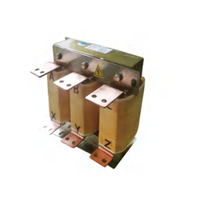
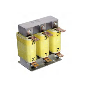
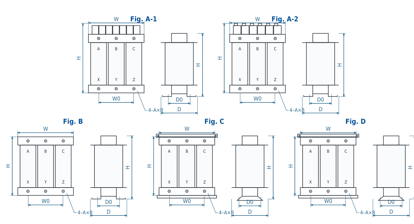
A/B/C are three-phase input terminals; X/Y/Z are three-phase output terminals. Models marked “separate capacitor” require space for the separate capacitor arrangement.
Outline and mounting dimensions
Discuss your drive system
Get the right accessory for your application
Send the drive model, voltage, rated current and project requirements. For motor-side filters, include the switching frequency and motor-cable length; for input-side harmonic filtering, include the rectifier type and harmonic target.