
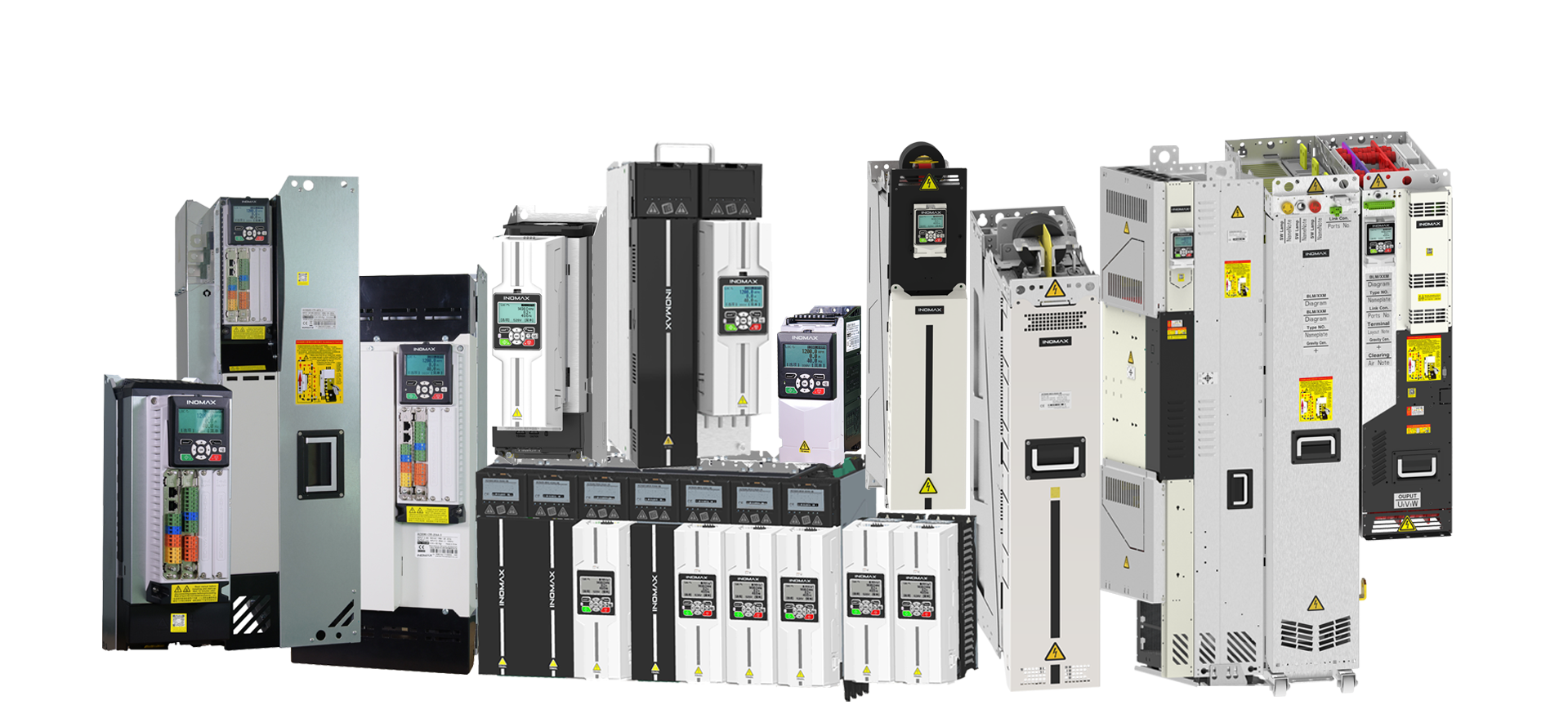
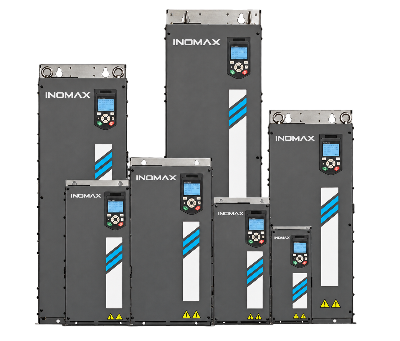
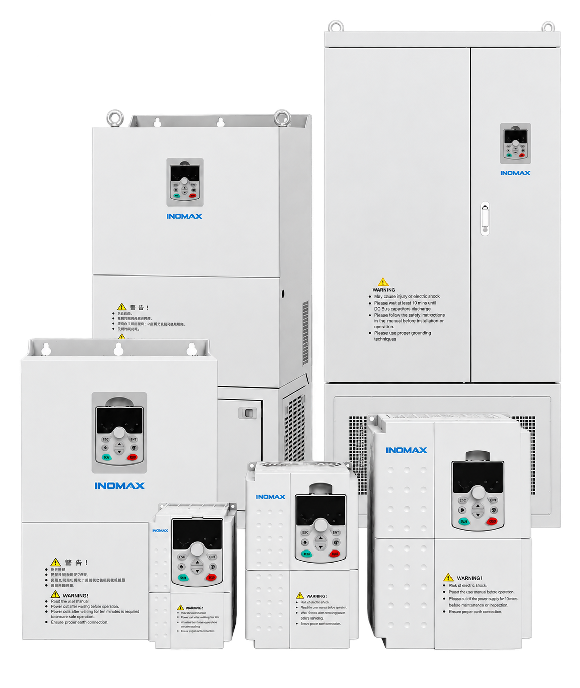
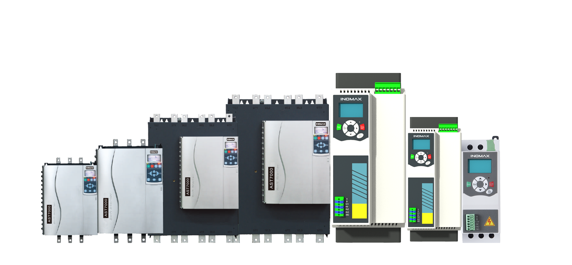

← MAX-MV series overview · Explore all 10 selection guides
01 · Product overview
Control air delivery and the cost of interruption.
MAX-MV supports large fans and blowers in power plants, cement production, steel plants, petrochemical utilities and mine ventilation. Variable-speed control adjusts air delivery to process demand, while configurable starting, restart and protection functions help coordinate the fan with the plant operating sequence.
For a fan OEM or EPC contractor, inertia and process availability deserve as much attention as rated power. A fan may coast for a long time, rotate backwards under draft or need a defined minimum airflow during a disturbance. These conditions determine the acceleration settings, flying-start behaviour, bypass strategy and required redundancy.
02 · Rating and cabinet selection
Power, voltage and current selection
Match the motor nameplate current, overload duty and site derating before confirming a model. The filters below help you compare the listed selections; final cabinet and option details are agreed for the project.
7 reference selections
No matching selection in this table. Send your motor data for engineering review.
Dimensions exclude top fans, bypass additions and service clearances. At 6.6 kV from 2,800 kW and 11 kV from 4,500 kW, add an 800 mm current-limiting cabinet with matching depth and height. Use the approved project drawing for the complete installation.
03 · Application fit
Application requirements that shape the package
ID and FD fans
Boiler, incinerator and process-air systems. Coordinate furnace pressure, airflow, purge permissions and plant interlocks.
Cement and metals ventilation
Kiln, raw-mill, preheater, cooler and dust-extraction fans. Review dust exposure, service access and continuous-duty requirements.
Mine and process blowers
Ventilation and process-air duties where restart permission, minimum airflow and failure response must be explicitly defined.
04 · Integration and options
Functions, accessories and engineering decisions
Select the starting torque and ramp together
High inertia can require a long acceleration even when the fan load torque is low at low speed. Review the motor thermal duty and drive current through the complete start. Avoid choosing a short ramp solely because the drive parameter permits it.
Use flying start for a coasting or reversing fan
The drive identifies motor rotation before applying the controlled output. This can reduce the wait for a complete stop after an interruption. The plant must still authorize restart, and the fan manufacturer’s mechanical limits remain part of the design.
Define the minimum operating condition after a fault
Cell bypass may allow continued operation with reduced available voltage. Establish whether the remaining fan speed and airflow are sufficient. If they are not, evaluate a standby drive, line bypass or a different redundancy arrangement.
Coordinate process control and mechanical limits
Set the pressure/flow feedback, PID tuning, minimum speed and approved resonance-avoidance bands. Agree the response to sensor failure, communication loss and local/remote transfer. Forced restart must not defeat the plant’s process protection.
Define the equipment scope
| Configuration item | What to agree |
|---|---|
| Motor control and feedback | Motor technology, control mode and encoder interface where required |
| Bypass / isolation | Manual or automatic line bypass, isolation and switching interlocks; selected for the process |
| Control integration | Standard Modbus RTU / I/O; optional PROFIBUS DP or exact TCP/IP arrangement |
| Continuity options | Cell-bypass strategy, controller redundancy or standby drive as project-selected |
| Service package | Spare cells, fans, boards, commissioning and training scope |
05 · Electrical performance
Performance for a defined operating duty
| Performance item | Selection basis |
|---|---|
| Motor-control modes | V/F; V/F with feedback; sensorless vector; closed-loop vector |
| Overload capability | 120% for 120 s; 150% for 5 s, checked against selected configuration and duty |
| Frequency resolution | 0.01 Hz; resolution is distinct from motor-speed accuracy |
| Acceleration / deceleration | 0.1–3,600 s; set within motor and process limits |
| Inverter efficiency | 98.5%; excludes the phase-shifting transformer |
| Power factor | ≥0.96 at the specified operating conditions |
| Harmonic performance | THD ≤4% for 3–4.16 kV; ≤2% for 6–13.8 kV. Confirm measurement point, loading and network conditions. |
Confirm performance at the required motor duty, supply conditions and cooling arrangement. For regenerative or braking loads, specify the operating cycle so a suitable two- or four-quadrant power stage can be selected.
06 · Technical data
Installation, environment and maintenance
| Item | Requirement / configuration |
|---|---|
| Operating temperature | −10 to +40°C; higher temperature requires an approved cooling and derating plan |
| Humidity | 20–90% RH, non-condensing, as the installation basis; confirm higher-humidity configurations |
| Altitude | Provide the site elevation; above 1,000 m, review insulation, cooling and derating for the selected configuration |
| Storage | −40 to +70°C; dry, protected storage without condensation or outdoor exposure |
| Cooling and enclosure | Forced air or water cooling; IP31 standard, IP42 optional, custom IP54 |
| Control supply | 220 V AC, 3 kVA, 50/60 Hz; optional DC supply by project arrangement |
| Control interfaces | 3 analog inputs / 4 analog outputs; 8 digital inputs / 5 digital outputs; RS485 / Modbus RTU standard |
| Installation | Indoor electrical room; no explosive/corrosive gases, conductive dust or oil mist; keep cooling and service access clear |
Plan safe service access, delivery openings, foundation loading and separate power/control cable routes. Inspection intervals and replacement work follow the installed equipment manual and the site maintenance plan.
07 · Supplier and configuration comparison
Compare complete proposals on the same basis
| Comparison point | What to check |
|---|---|
| Starting duty | Compare the same motor inertia, permitted start time and current limit. |
| Recovery | Check forward/reverse flying start, voltage-dip response and restart permissions. |
| Continuity | Define the actual airflow and speed available after a fault or transfer. |
| Efficiency | Use measured fan duty points and total input power for the energy assessment. |
Ask each supplier to identify inclusions, exclusions and deviations. The selected rating, options, installation work, acceptance test and service responsibilities should be clear before comparing the final price.
08 · Customer applications
Relevant industrial project experience
Jinling Petrochemical
10 kV · 630 kW
MAX-MV-100-630-C8601A and C8601B drives were commissioned for incinerator induced-draft fans at the petrochemical plant.
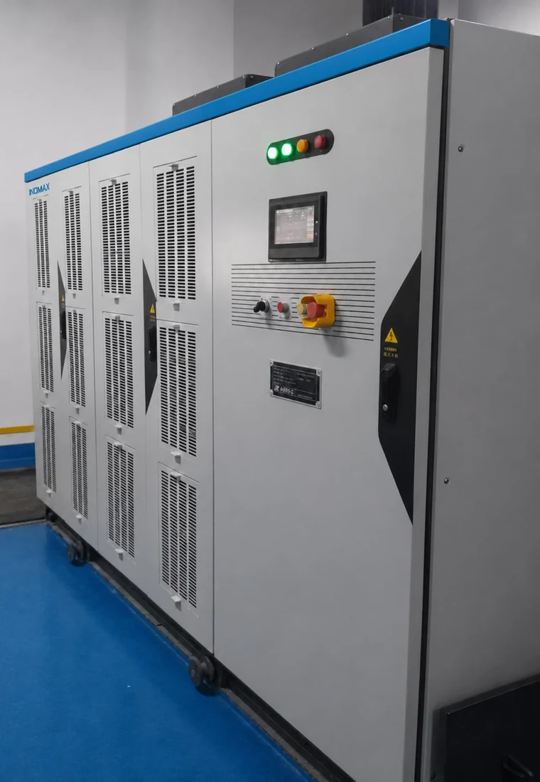
Discuss a comparable configuration with INOMAX. The motor, equipment scope and operating conditions are assessed separately for each project.
Practical project FAQ
Questions to resolve before ordering
6 questions
Can MAX-MV start an induced-draft fan that is rotating backwards?
Flying start supports detection of forward rotation, reverse rotation and standstill. The restart sequence must be configured for the actual fan and process, with the required permissives and mechanical limits checked before commissioning.
How should we size a VFD for a high-inertia fan?
Provide motor current, combined inertia, fan torque/speed information, permissible acceleration time and starts per operating cycle. Check drive overload and motor heating across the start, then confirm the thermal duty at normal operation.
Can automatic bypass keep a boiler fan running?
An automatic bypass arrangement can be evaluated, but motor voltage, direct-line operation, transfer sequence, switchgear interlocks and the process disturbance must all be acceptable. The project must define whether transfer is stopped, synchronized or uses another engineered sequence.
Will cell bypass preserve the required ventilation flow?
That depends on the remaining output capability and the fan system. Define the minimum fan speed and airflow required by the plant, then assess the permitted cell-bypass states against that operating point.
Does INOMAX have a petrochemical fan reference?
The Jinling Petrochemical incinerator induced-draft fan application used MAX-MV-100-630-C8601A and C8601B drives, corresponding to the 10 kV, 630 kW selection. This is an application reference; the configuration for a new fan must be assessed separately.
Can a fan OEM integrate the drive with its packaged controls?
Yes, the interface can be developed around the OEM’s operating sequence. Agree the command source, sensor scaling, alarm/trip signals, communication map, permissives and test sequence so the fan package and drive can be commissioned together.
No matching question. Ask our application team.
Technical resources
Catalog, manual & project support
MAX-MV catalog
Ratings, dimensions, features and configuration options.
MAX-MV user manual
Installation, operation, control settings and maintenance.
Project-specific documents
Contact INOMAX for project records, drawings, certificates and test reports matched to your application.
09 · Start the conversation
Let’s define your next MAX-MV project.
Discuss Your Fan Duty & Continuity Needs
Send the motor rating, fan inertia, process airflow requirement and preferred restart or bypass strategy.
Email: info@inomaxtechnology.com
Build your local MAX-MV business
Discuss the industries you serve, application-engineering support, training, commissioning and spare-parts planning. Commercial and service arrangements are defined for your market and projects.


