

← MAX-MV series overview · Explore all 10 selection guides
01 · Product overview
A megawatt rating is the start of the selection.
The same motor power can require very different drive current, cell arrangements and cabinet sizes at different voltages. MAX-MV high-power selections therefore begin with the motor nameplate and operating cycle, followed by the supply network, cooling method and continuity requirement.
This page focuses on 1–10 MW selections within the established voltage-specific ranges. The 3 and 3.3 kV lists extend to 3.15 MW, 4.16 kV to 4 MW, 6 and 6.6 kV to 6.3 MW, and 10 and 11 kV to 10 MW. Higher series capability is assessed separately as an engineered project.
02 · Rating and cabinet selection
Power, voltage and current selection
Match the motor nameplate current, overload duty and site derating before confirming a model. The filters below help you compare the listed selections; final cabinet and option details are agreed for the project.
23 reference selections
No matching selection in this table. Send your motor data for engineering review.
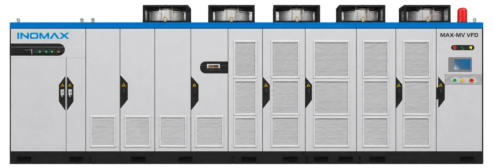
Dimensions exclude top fans, bypass additions and service clearances. At 6.6 kV from 2,800 kW and 11 kV from 4,500 kW, add an 800 mm current-limiting cabinet with matching depth and height. Use the approved project drawing for the complete installation.
03 · Application fit
Application requirements that shape the package
1–2 MW utilities
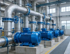
Large pumps, ventilation fans and process packages. Compare starting requirements and actual part-load operation.
4–6.3 MW industrial machinery
Compressors, large fans and high-power motor packages where incoming-network strength and installation space become major design inputs.
8–10 MW process systems
Large compressor and industrial drive projects at suitable voltage classes. Confirm motor technology, cooling, protection and the testing arrangement early.
04 · Integration and options
Functions, accessories and engineering decisions
Size for current and the complete operating cycle
Review continuous current, acceleration, peak process load, overload duration and recovery time. The specified 120% for 120 s and 150% for 5 s capabilities must be checked against the selected configuration and thermal duty. A 200% current threshold is immediate protection, not an operating allowance.
Check weak-grid starting and transformer energization
The motor starting sequence and transformer inrush affect different parts of the electrical system. Provide grid capacity or generator information, transformer details and permitted voltage dip. Include current-limiting equipment where the rating and source require it.
Use total package losses for thermal design
The 98.5% inverter efficiency does not include every loss in the installation. Obtain transformer, inverter and auxiliary losses at the required duty points. Allocate heat to the room, exhaust duct and water circuit before sizing HVAC or a heat exchanger.
Plan the route from factory to foundation
Large cabinets require an agreed transport split, dimensions, mass, lifting method and receiving access. Check door openings, turning space, cable trenches and service clearances before manufacture. Include the bypass and current-limiting sections in the overall layout.
Define the equipment scope
| Configuration item | What to agree |
|---|---|
| Motor control and feedback | Motor technology, control mode and encoder interface where required |
| Bypass / isolation | Manual or automatic line bypass, isolation and switching interlocks; selected for the process |
| Control integration | Standard Modbus RTU / I/O; optional PROFIBUS DP or exact TCP/IP arrangement |
| Continuity options | Cell-bypass strategy, controller redundancy or standby drive as project-selected |
| Service package | Spare cells, fans, boards, commissioning and training scope |
05 · Electrical performance
Performance for a defined operating duty
| Performance item | Selection basis |
|---|---|
| Motor-control modes | V/F; V/F with feedback; sensorless vector; closed-loop vector |
| Overload capability | 120% for 120 s; 150% for 5 s, checked against selected configuration and duty |
| Frequency resolution | 0.01 Hz; resolution is distinct from motor-speed accuracy |
| Acceleration / deceleration | 0.1–3,600 s; set within motor and process limits |
| Inverter efficiency | 98.5%; excludes the phase-shifting transformer |
| Power factor | ≥0.96 at the specified operating conditions |
| Harmonic performance | THD ≤4% for 3–4.16 kV; ≤2% for 6–13.8 kV. Confirm measurement point, loading and network conditions. |
Confirm performance at the required motor duty, supply conditions and cooling arrangement. For regenerative or braking loads, specify the operating cycle so a suitable two- or four-quadrant power stage can be selected.
06 · Technical data
Installation, environment and maintenance
| Item | Requirement / configuration |
|---|---|
| Operating temperature | −10 to +40°C; higher temperature requires an approved cooling and derating plan |
| Humidity | 20–90% RH, non-condensing, as the installation basis; confirm higher-humidity configurations |
| Altitude | Provide the site elevation; above 1,000 m, review insulation, cooling and derating for the selected configuration |
| Storage | −40 to +70°C; dry, protected storage without condensation or outdoor exposure |
| Cooling and enclosure | Forced air or water cooling; IP31 standard, IP42 optional, custom IP54 |
| Control supply | 220 V AC, 3 kVA, 50/60 Hz; optional DC supply by project arrangement |
| Control interfaces | 3 analog inputs / 4 analog outputs; 8 digital inputs / 5 digital outputs; RS485 / Modbus RTU standard |
| Installation | Indoor electrical room; no explosive/corrosive gases, conductive dust or oil mist; keep cooling and service access clear |
Plan safe service access, delivery openings, foundation loading and separate power/control cable routes. Inspection intervals and replacement work follow the installed equipment manual and the site maintenance plan.
07 · Supplier and configuration comparison
Compare complete proposals on the same basis
| Comparison point | What to check |
|---|---|
| Capacity | Use the same voltage, motor current and overload duty for each quotation. |
| Efficiency | Require identical measurement boundaries and loading when comparing losses. |
| Installation cost | Include transport, lifting, civil work, cooling, cabling and switchgear changes. |
| Downtime exposure | Compare spares, transfer strategy, commissioning and recovery arrangements. |
Ask each supplier to identify inclusions, exclusions and deviations. The selected rating, options, installation work, acceptance test and service responsibilities should be clear before comparing the final price.
08 · Customer applications
Relevant industrial project experience
Yili Chuanning Biotechnology
10 kV · 8,000 kW
MAX-MV-100-8000 was selected for the Xi’an Shaangu Power steam-compressor project serving secondary-settlement effluent treatment and an MVR evaporation system.
Discuss a comparable configuration with INOMAX. The motor, equipment scope and operating conditions are assessed separately for each project.
Practical project FAQ
Questions to resolve before ordering
6 questions
Which voltages support a 4 MW MAX-MV selection?
The voltage-specific lists include 4 MW at 4.16, 6, 6.6, 10 and 11 kV. The 3 and 3.3 kV lists stop at 3.15 MW. Verify the motor current and configuration; the same 4 MW label does not imply interchangeable drive hardware.
Can I select the next larger kW model for a heavy-duty motor?
A larger power label alone is not sufficient. Check nameplate current, starting torque, overload duration, speed range and environmental derating. The heavy-duty suffix and final current capability should be confirmed against the actual load cycle.
What is the current of an 8 MW 10 kV selection?
MAX-MV-100-8000 has a reference current of 580 A. Its base cabinet dimensions are 7780 × 1800 × 2500 mm, excluding additional bypass equipment and top fans. The final arrangement depends on project options.
Can a 10 MW drive operate from a 6.6 kV motor supply?
The established 6.6 kV selection list extends to 6.3 MW. A 10 MW, 6.6 kV request needs a separate engineering assessment; it should not be quoted using a 10 or 11 kV standard model.
How much electrical-room cooling is needed for a multi-megawatt drive?
Use the selected package’s heat-loss schedule and the site ventilation conditions. Transformer losses, auxiliary loads, enclosure design and the split between room and external heat rejection all matter. The inverter efficiency alone cannot determine the HVAC duty.
What should we freeze before the production schedule starts?
Confirm motor and supply data, current rating, cooling and bypass scope, cabinet drawings, control interfaces, test plan and shipping requirements. The agreed document and approval milestones provide the basis for a realistic production and shutdown schedule.
No matching question. Ask our application team.
Technical resources
Catalog, manual & project support
MAX-MV catalog
Ratings, dimensions, features and configuration options.
MAX-MV user manual
Installation, operation, control settings and maintenance.
Project-specific documents
Contact INOMAX for project records, drawings, certificates and test reports matched to your application.
09 · Start the conversation
Let’s define your next MAX-MV project.
Get a Motor-Based Sizing Proposal
Send the motor power and current, supply voltage, duty cycle and planned installation date. We will review the complete high-power package.
Email: info@inomaxtechnology.com
Build your local MAX-MV business
Discuss the industries you serve, application-engineering support, training, commissioning and spare-parts planning. Commercial and service arrangements are defined for your market and projects.


