




← MAX-MV series overview · Explore all 10 selection guides
01 · Product overview
Match pump output to the process demand.
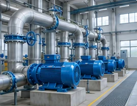
MAX-MV provides variable-speed control for large pumps in water supply, wastewater, district heating and industrial processes. The controller can regulate speed from pressure, flow or level feedback, allowing the pump system to follow demand within the operating limits set by the pump and motor manufacturers.
A useful pump-drive proposal starts with the hydraulic system. Static head, the system curve, minimum flow, operating hours and the present throttling or bypass method determine both the control strategy and the energy opportunity. INOMAX can review these inputs with the pump OEM or EPC team before the electrical package is finalized.
02 · Rating and cabinet selection
Power, voltage and current selection
Match the motor nameplate current, overload duty and site derating before confirming a model. The filters below help you compare the listed selections; final cabinet and option details are agreed for the project.
7 reference selections
No matching selection in this table. Send your motor data for engineering review.
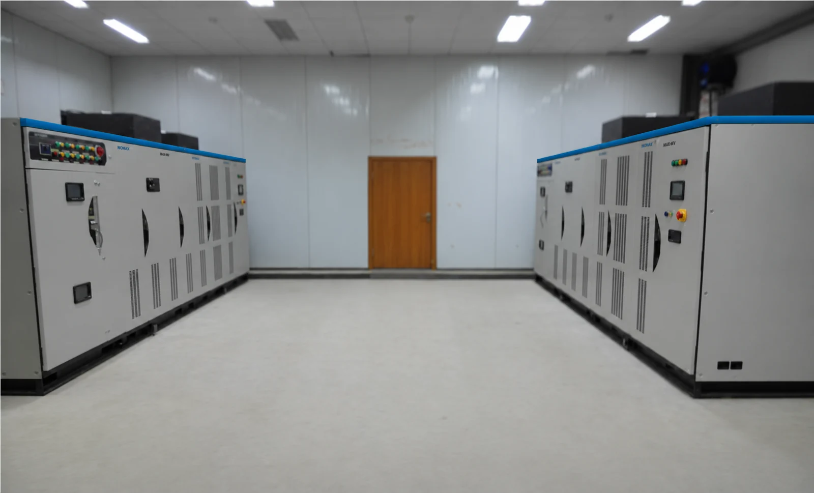
Dimensions exclude top fans, bypass additions and service clearances. At 6.6 kV from 2,800 kW and 11 kV from 4,500 kW, add an 800 mm current-limiting cabinet with matching depth and height. Use the approved project drawing for the complete installation.
03 · Application fit
Application requirements that shape the package
Water intake and transfer
Large intake, transmission and distribution pumps with varying demand. Define minimum pressure, static lift and operating duty points.
Circulation and heating
Cooling-water, district-heating and industrial circulation systems. Coordinate differential-pressure control and the number of pumps in service.
Wastewater and process pumping
Sewage, feedwater, brine, oil and other industrial pumping duties. Match speed and torque control to the actual pump type, fluid and process constraints.
04 · Integration and options
Functions, accessories and engineering decisions
Keep operation inside the pump envelope
Agree minimum and maximum speed, minimum stable flow, allowable pressure and the required suction conditions. A drive does not remove cavitation, dry-running or minimum-flow risks. Coordinate protective sensors and process trips with the pump package.
Tune PID to the hydraulic system
Select the control variable and sensor position, define signal scaling and agree the response to sensor failure. Pressure, flow or level control should use suitable ramp and output limits so the drive and control valve do not fight each other.
Plan multi-pump and bypass operation
Decide whether each pump needs independent variable-speed operation or whether an engineered starting/transfer arrangement meets the duty. Define lead/lag logic, standby rotation, check-valve behaviour and the transition to bypass before selecting switching equipment.
Build an energy case from measured operation
Compare input power at the actual flow duty points and annual operating hours. The ideal centrifugal-pump affinity relationship is a starting model; static head, pump efficiency, motor losses and control limits change the system result. Use a documented baseline for the payback calculation.
Define the equipment scope
| Configuration item | What to agree |
|---|---|
| Motor control and feedback | Motor technology, control mode and encoder interface where required |
| Bypass / isolation | Manual or automatic line bypass, isolation and switching interlocks; selected for the process |
| Control integration | Standard Modbus RTU / I/O; optional PROFIBUS DP or exact TCP/IP arrangement |
| Continuity options | Cell-bypass strategy, controller redundancy or standby drive as project-selected |
| Service package | Spare cells, fans, boards, commissioning and training scope |
05 · Electrical performance
Performance for a defined operating duty
| Performance item | Selection basis |
|---|---|
| Motor-control modes | V/F; V/F with feedback; sensorless vector; closed-loop vector |
| Overload capability | 120% for 120 s; 150% for 5 s, checked against selected configuration and duty |
| Frequency resolution | 0.01 Hz; resolution is distinct from motor-speed accuracy |
| Acceleration / deceleration | 0.1–3,600 s; set within motor and process limits |
| Inverter efficiency | 98.5%; excludes the phase-shifting transformer |
| Power factor | ≥0.96 at the specified operating conditions |
| Harmonic performance | THD ≤4% for 3–4.16 kV; ≤2% for 6–13.8 kV. Confirm measurement point, loading and network conditions. |
Confirm performance at the required motor duty, supply conditions and cooling arrangement. For regenerative or braking loads, specify the operating cycle so a suitable two- or four-quadrant power stage can be selected.
06 · Technical data
Installation, environment and maintenance
| Item | Requirement / configuration |
|---|---|
| Operating temperature | −10 to +40°C; higher temperature requires an approved cooling and derating plan |
| Humidity | 20–90% RH, non-condensing, as the installation basis; confirm higher-humidity configurations |
| Altitude | Provide the site elevation; above 1,000 m, review insulation, cooling and derating for the selected configuration |
| Storage | −40 to +70°C; dry, protected storage without condensation or outdoor exposure |
| Cooling and enclosure | Forced air or water cooling; IP31 standard, IP42 optional, custom IP54 |
| Control supply | 220 V AC, 3 kVA, 50/60 Hz; optional DC supply by project arrangement |
| Control interfaces | 3 analog inputs / 4 analog outputs; 8 digital inputs / 5 digital outputs; RS485 / Modbus RTU standard |
| Installation | Indoor electrical room; no explosive/corrosive gases, conductive dust or oil mist; keep cooling and service access clear |
Plan safe service access, delivery openings, foundation loading and separate power/control cable routes. Inspection intervals and replacement work follow the installed equipment manual and the site maintenance plan.
07 · Supplier and configuration comparison
Compare complete proposals on the same basis
| Comparison point | What to check |
|---|---|
| Process performance | Compare flow/pressure control over the required operating envelope. |
| Energy assessment | Use identical flow duty points, operating hours and total electrical losses. |
| Control scope | Include sensors, PID responsibility, multi-pump logic and failure response. |
| Project cost | Include bypass, installation, cooling, commissioning and service access. |
Ask each supplier to identify inclusions, exclusions and deviations. The selected rating, options, installation work, acceptance test and service responsibilities should be clear before comparing the final price.
08 · Customer applications
Relevant industrial project experience
Industrial water-pump application
MAX-MV-060-900
A 6 kV, 900 kW MAX-MV selection is listed for the Yangzi Petrochemical water-pump project. This provides a relevant starting point for discussing a large pump package.
Feedwater pump application
MAX-MV-100-4000
The Lianyungang Petrochemical Industry Base Utilities Island Phase I project includes a 10 kV, 4,000 kW feedwater-pump drive selection.
Discuss a comparable configuration with INOMAX. The motor, equipment scope and operating conditions are assessed separately for each project.
Practical project FAQ
Questions to resolve before ordering
6 questions
How much electricity can a medium-voltage pump VFD save?
Savings depend on the hydraulic system and operating profile. Collect flow, pressure, input power and operating hours under the existing control method, then compare the proposed speed-controlled duty points. A high static head or narrow operating range can reduce the opportunity; a fixed percentage should not be applied to every pump.
Will slowing the pump always reduce flow as expected?
The operating point depends on the pump curve and system curve. Minimum speed may be set by static head, stable operation, cooling or process requirements. Have the pump OEM approve the speed envelope before finalizing the drive settings.
Can MAX-MV help reduce water hammer?
Controlled acceleration and deceleration can support smoother flow changes, but hydraulic transients also depend on the pipeline, valves, check valves and pump inertia. Use the hydraulic analysis to define acceptable ramps and stopping behaviour; the VFD alone does not guarantee elimination of water hammer.
Can one VFD control several pumps?
Several arrangements are possible, but independent continuous speed control generally requires a drive for each independently controlled motor. A one-drive/multiple-motor starting or transfer scheme needs engineered switching, interlocking and a defined operating sequence.
Can we retain our existing water-pump motor and DCS?
They can be assessed for reuse. Provide motor data, insulation condition, cable details, the I/O list and communication requirements. Verify low-speed motor cooling, protection and control-source priority as part of the retrofit design.
What should a pump OEM send with an enquiry?
Send the motor nameplate, pump curves, fluid and duty points, speed limits, starting conditions and system-control description. Include site voltage, cooling, ambient conditions and the scope expected from the drive supplier.
No matching question. Ask our application team.
Technical resources
Catalog, manual & project support
MAX-MV catalog
Ratings, dimensions, features and configuration options.
MAX-MV user manual
Installation, operation, control settings and maintenance.
Project-specific documents
Contact INOMAX for project records, drawings, certificates and test reports matched to your application.
09 · Start the conversation
Let’s define your next MAX-MV project.
Request a Pump-System Drive Proposal
Share your pump curve, motor data and flow/pressure duty points. We will review the drive rating, process interface and project scope.
Email: info@inomaxtechnology.com
Build your local MAX-MV business
Discuss the industries you serve, application-engineering support, training, commissioning and spare-parts planning. Commercial and service arrangements are defined for your market and projects.


