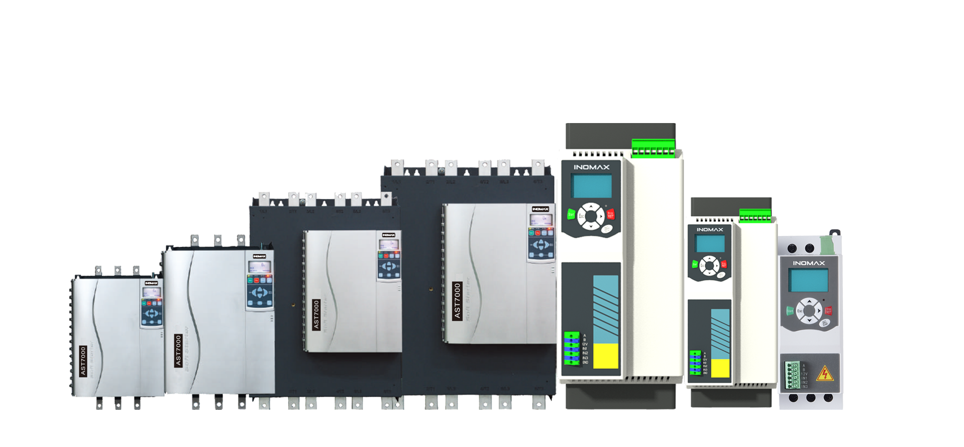




ACS890 / High-power parallel
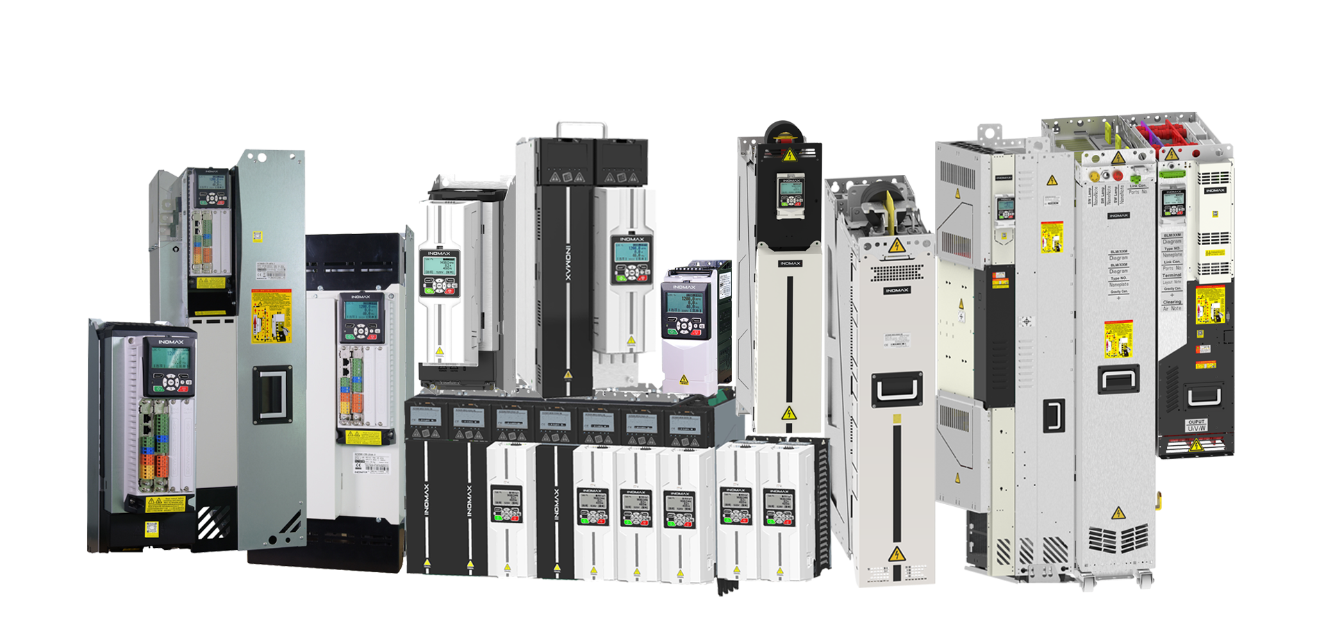
From individual modules to a high-power drive cabinet
Scale the power stage around the required motor current and operating duty. ACS890 supports 1–16 eligible parallel inverter or AFE power units, with configuration-specific rules for current sharing, protection and cooling.
High-power drive selection starts with the load envelope: continuous current, peak current, overload duration, repetition rate, speed range and any returned energy. A module’s nominal kW is a useful catalog reference, but it does not by itself determine the motor power available in a complete cabinet.
For applicable parallel inverter or AFE systems, the catalog uses 0.97 × module count × rated current. For example, two eligible 780 A modules give a preliminary continuous-current basis of 0.97 × 2 × 780 = 1513.2 A, before the other required derating and duty checks. This is an illustrative current calculation, not an approved cabinet rating or a motor-kW guarantee.
The catalog identifies a liquid-cooled three-level 3.3 kV configuration with up to 4 MW per cabinet. Low-voltage module tables, the number of coordinated motors and this medium-voltage cabinet statement describe different things. The selected voltage and topology must remain explicit throughout the quotation and technical specification.
Power-module coordination
FLYLINK provides less than 10 ns inter-node clock difference and approximately 2.5 μs average node data exchange. These are network timing figures, not guaranteed mechanical synchronization accuracy.
Duty-aware engineering
Review the light-duty or heavy-duty reference, thermal conditions, switching requirements and repeated overloads before selecting the number of modules.
Serviceable cabinet design
Plan isolation, branch protection, connection access, module replacement and spare parts together with the electrical and cooling architecture.
System configuration
Define the power path and supporting equipment.
Functional configuration guide, not an installation wiring diagram. Final protection, connections and component compatibility follow the engineered system documentation.
Selection data
Representative modules for parallel-system engineering
| Model | Class / cooling | PN (kW) | Continuous current | LD kW / A | HD kW / A | W × D × H (mm) / weight |
|---|---|---|---|---|---|---|
| ACS890-R84-0915-4 | 400 V AC / Air | 500 | 915 IN (A) | 500 / 868 | 450 / 731 | 170×585×980 / 73.0 kg |
| ACS890-L72-0915-4 | 400 V AC / Liquid | 500 | 915 IN (A) | 500 / 868 | 450 / 731 | 170×510×930 / 55.0 kg |
| ACS890-R89-0590-7 | 700 V AC / Air | 560 | 590 IN (A) | 560 / 572 | 500 / 513 | 170×585×980 / 75.0 kg |
| ACS890-L78-0780-7 | 700 V AC / Liquid | 800 | 780 IN (A) | 800 / 757 | 710 / 679 | 170×510×930 / 55.0 kg |
| ACS890-T88-0823-11 | 1140 V AC / Liquid | 1300 | 823 IN (A) | 1300 / 798 | 1000 / 617 | 170×545×1090 / 75.0 kg |
| ACS890-T98-0950-11 | 1140 V AC / Liquid | 1500 | 950 IN (A) | 1500 / 921 | 1200 / 712 | 240×630×1260 / 130.0 kg |
Read the current correctly: inverter values are motor IN; AFE values are AC / DC currents. LD and HD cells show the catalog power / current references. Continuous ratings use the catalog conditions; where specified, LD is 110% for 1 minute in 5 and HD is 150% for 1 minute in 5. Apply ambient, installation and topology-specific derating. Dimensions are for modules, not complete cabinets.
Accessories & integration
Specify the complete system package.
| Component / option | Role and selection requirement |
|---|---|
| CU200 + FLYLINK cabling | Control and synchronized communications for the eligible parallel assembly. |
| Topology-specific reactors / mounting bases | The catalog includes BL96, BL9A, PL96, PL9A, PL96-LA and PL9A-LA options. Select only those required by the actual current-sharing arrangement. |
| CHG10 / CHG20 / CHG30 | Active precharge families associated with 400–700 V, 1140 V and 3300 V respectively. |
| Grid filter and measurement | A regenerative ALM arrangement requires the matched SLC, CHG and VSM configuration. |
| Cooling loop and residual heat management | Rate the complete cooling system for the actual module losses and operating conditions; cooler model names are not drive output ratings. |
| Protection and service interfaces | Branch protection, interlocks, access clearances and test points are defined in the cabinet engineering package. |
| CP68 and feedback extensions | Local operation, event review and motor feedback appropriate to the duty. |
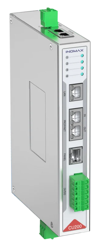
Control, feedback and power must match.
Include the PLC interface, encoder, operator panel, auxiliary supply, precharge and installation hardware in the quotation. Availability and compatibility depend on the selected module and cabinet configuration.
Application engineering
Match the configuration to the duty.
Large motor drives
Use eligible modules to meet the required current at the chosen voltage, subject to overload and thermal checks.
Regenerative test systems
Size the motor-side stage and grid-side AFE from their own duty profiles, including sustained returned power.
Steel, mining and heavy machinery
Review starting / overload demand, the mechanical coupling and the maintenance strategy before fixing the cabinet arrangement.
Product FAQ
Questions about high-power parallel.
Does 1–16 parallel units mean 16 motors?
No. Parallel power units can contribute current to one engineered power stage. The catalog’s separate motor-coordination limit is 1–4 motors in the applicable configuration.
Can I multiply a module’s kW by the module count?
That is not a complete selection method. Start with motor current and duty, apply the catalog parallel factor where relevant, then check thermal derating, overload, voltage, power-path limits and the cabinet design.
Can every ACS890 topology be connected in parallel?
No. Eligible INV and AFE units have defined parallel arrangements. Integrated drives are not paralleled. BLM / SLM grid-side arrangements require individual AC reactors; DC/DC load-side paralleling requires specified DC LC filters, and direct BRK paralleling is prohibited.
Where does the up-to-4 MW cabinet rating apply?
It applies to the catalog’s 3.3 kV liquid-cooled three-level configuration. It must not be presented as the rating of every 400 V, 690 V or 1140 V cabinet.
Does a parallel assembly automatically provide redundancy?
No automatic redundancy claim is made. Fault response, isolation, operation after a module fault and spare-module strategy must be defined and validated for the specific system.
How are braking and regeneration selected?
Provide the maximum and continuous returned power plus the operating cycle. The AFE, shared DC link and any braking-resistor path have to be assessed together.
Which documents can be supplied for a project?
Request the selected module data, cabinet dimensions, cooling requirements, interface list and applicable manuals / certificates. Drawings and approval scope are matched to the confirmed configuration.
What determines production time and warranty?
Cabinet layout, module availability, cooling, protection, interfaces and testing determine the schedule after technical approval. The standard warranty is two years, with coverage and service arrangements defined in the order.
Engineering enquiry
Request the right configuration.
Voltage; continuous/peak current; overload timing; speed range; returned power; cooling; cabinet dimensions; service requirements; project schedule.
info@inomaxtechnology.com
Talk to INOMAX on WhatsApp →
Include your company and the page topic in the message. Manuals, drawings and certificates are supplied for the selected configuration.