




ACS890 / Common DC bus / multi-motor
Power sharing and motion coordination are separate design choices
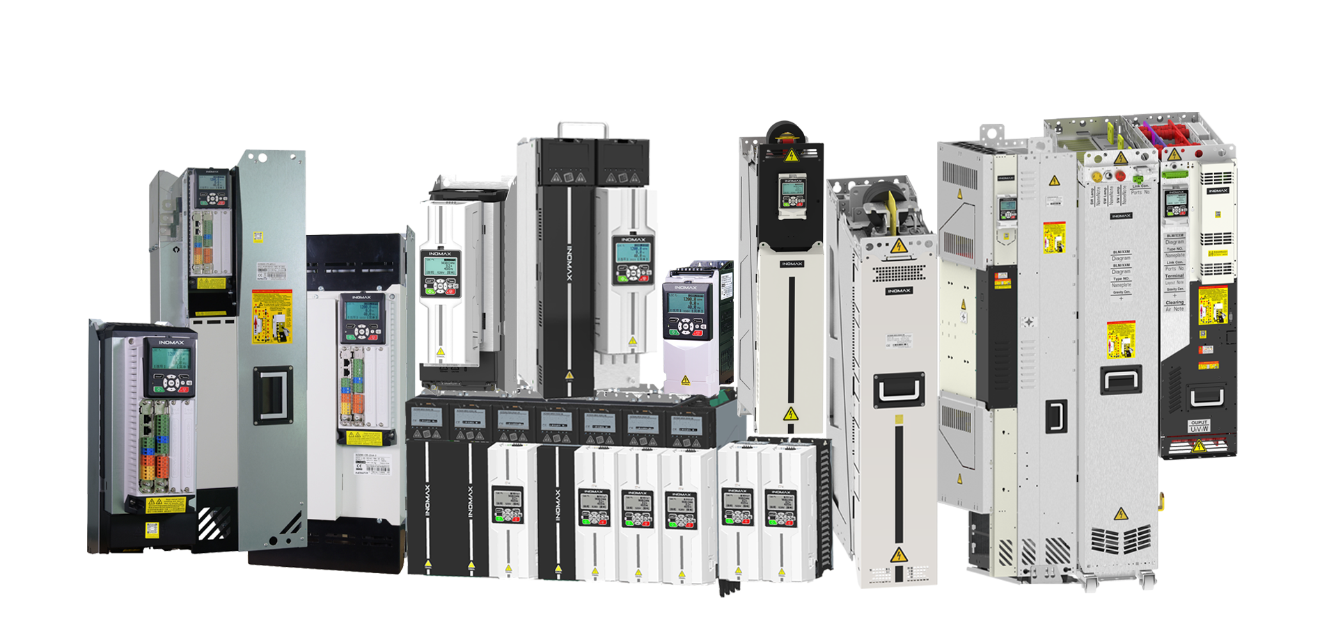
Coordinate the motor group and manage energy across the machine. ACS890 combines a modular DC-link architecture with torque, speed and position-following functions for engineered multi-drive systems.
A common DC bus connects compatible converter branches to a shared power link. One motor branch may consume energy while another returns it, allowing energy exchange within the system. The front end, DC-link protection and any braking path must still be selected for the complete operating cycle.
Motor coordination defines how the mechanical axes relate to one another. Torque following supports load sharing in rigidly coupled drives. Speed following coordinates flexibly coupled motion. Position / phase following allows a follower to track the master’s position while the master operates in speed control.
Parallel power modules are a different concept: several eligible modules may be combined to supply one power stage. The catalog’s 1–16 eligible parallel power-unit limit, 1–4 coordinated-motor limit and 32 nodes per FLYLINK network must not be presented as interchangeable counts.
FLYLINK handles synchronized communication between control, feedback and power modules. The catalog also describes configurable Ethernet master-follower data exchange. Select the communication architecture, signal mapping and timing around the actual machine and PLC rather than treating network timing as a mechanical accuracy guarantee.
Torque sharing
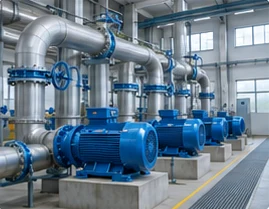
Balance motors driving a shared load, such as a conveyor or cutterhead, with a coordinated control and protection design.
Speed and position following
Define the mechanical coupling, feedback devices, reference relationship and permitted tracking error for each axis.
Commissioning visibility
The catalog commissioning tools support 12 waveform channels at 4000 samples per second with a shared time axis, helping compare drive behavior through the load cycle.
System configuration
Define the power path and supporting equipment.
Functional configuration guide, not an installation wiring diagram. Final protection, connections and component compatibility follow the engineered system documentation.
| Selection point | Configuration / option | Engineering consideration |
|---|---|---|
| One shared mechanical load | Torque following / load sharing | Specify coupling, load distribution and common protection response |
| Coordinated process axes | Speed following | Specify acceleration, deceleration, ratio and process feedback |
| Phase-related machinery | Position / phase following | Specify encoder resolution, reference relationship and tracking limits |
| Motoring and generating branches | Common DC bus energy sharing | Assess simultaneous operating points and remaining grid/braking duty |
| Higher current for one motor | Eligible parallel power modules | Apply topology rules and current-based sizing independently of motor count |
Selection data
Representative inverter modules for branch sizing
| Model | Class / cooling | PN (kW) | Continuous current | LD kW / A | HD kW / A | W × D × H (mm) / weight |
|---|---|---|---|---|---|---|
| ACS890-R53-0145-4 | 400 V AC / Air | 75 | 145 IN (A) | 75 / 138 | 55 / 116 | 125×265×540 / 12.0 kg |
| ACS890-R72-0487-4 | 400 V AC / Air | 250 | 487 IN (A) | 250 / 462 | 200 / 389 | 170×460×800 / 40.0 kg |
| ACS890-R78-0370-7 | 700 V AC / Air | 355 | 370 IN (A) | 355 / 359 | 315 / 322 | 125×460×800 / 31.0 kg |
| ACS890-L78-0780-7 | 700 V AC / Liquid | 800 | 780 IN (A) | 800 / 757 | 710 / 679 | 170×510×930 / 55.0 kg |
| ACS890-T87-0633-11 | 1140 V AC / Liquid | 1000 | 633 IN (A) | 1000 / 614 | 800 / 475 | 170×545×1090 / 75.0 kg |
Read the current correctly: inverter values are motor IN; AFE values are AC / DC currents. LD and HD cells show the catalog power / current references. Continuous ratings use the catalog conditions; where specified, LD is 110% for 1 minute in 5 and HD is 150% for 1 minute in 5. Apply ambient, installation and topology-specific derating. Dimensions are for modules, not complete cabinets.
Accessories & integration
Specify the complete system package.
| Component / option | Role and selection requirement |
|---|---|
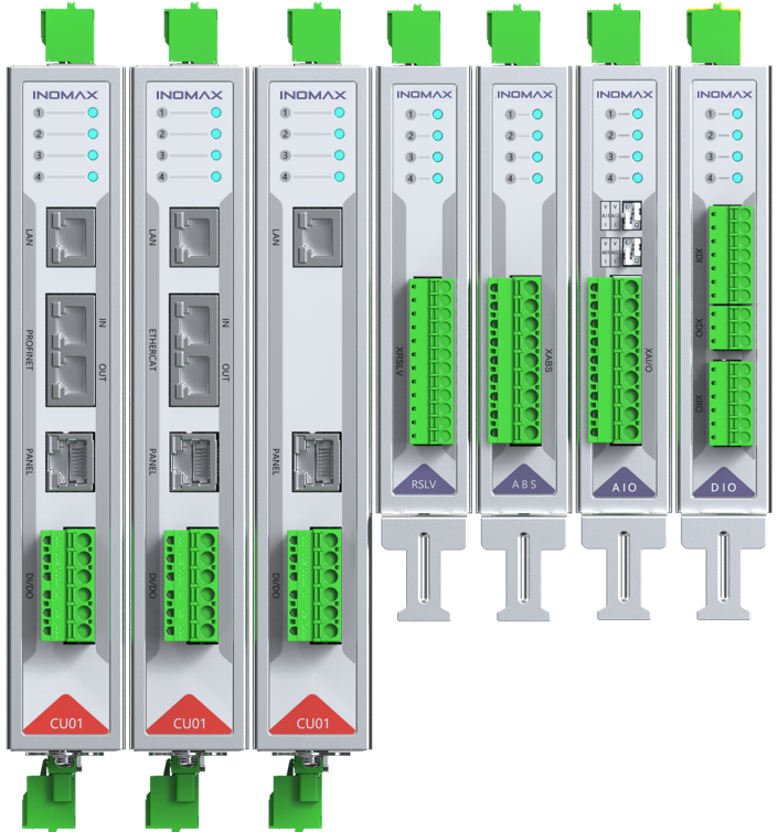
| CU200 family | Control-unit choice and number determined by the coordinated system architecture. |
| EX-HTL / EX-TTL / EX-RSLV / EX-SIN / EX-ABS | Feedback selected for each motor and following mode. |
| EX-DIO-01 / EX-AIO-01 | Interlocks, commands and process signals for the machine. |
| EX-CNC / EX-DP / EX-MOD / EX-CAN | Catalog pulse-position, PROFIBUS DP, Modbus RTU and CANopen extension options as required. |
| CA04-SF5 FLYLINK cables | Correct cable type and length for the module network; the catalog specifies shielded twisted pair, not optical fiber. |
| Precharge, grid filter and VSM | Supply-side supporting components matched to the chosen rectifier / AFE architecture. |
| DC branch protection and braking equipment | Defined at system level for the selected DC-link and energy cycle. |
| CP68 / Ethernet commissioning connection | Local operator access and the network arrangement needed for parameter and waveform work. |
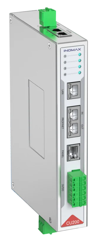
Control, feedback and power must match.
Include the PLC interface, encoder, operator panel, auxiliary supply, precharge and installation hardware in the quotation. Availability and compatibility depend on the selected module and cabinet configuration.
Application engineering
Match the configuration to the duty.
Steel mills and process lines
Coordinate rollers, coilers or other process axes while reviewing the shared energy and stopping duties.
Tunnel-boring cutterheads and conveyors
Balance motors on a common load and define overload response for the group.
Flywheel and test systems
Coordinate acceleration / deceleration and assess energy flow between motor, DC-link and grid-side branches.
Product FAQ
Questions about common dc bus / multi-motor.
What is the benefit of a common DC bus?
Compatible branches can exchange energy through a shared DC link, and the supply architecture can be engineered for the combined machine. Actual energy savings depend on the operating cycle and simultaneous motoring / generating demand.
How many motors can ACS890 coordinate?
The catalog specifies 1–4 coordinated motors in the applicable configuration. Larger or different machine architectures require an engineering review; the 1–16 parallel power-unit specification does not mean 16 coordinated motors.
When should I use torque following rather than speed following?
Torque following is intended for load sharing with rigid mechanical coupling. Speed following is used for coordinated motion with more flexible coupling. The correct choice depends on the mechanics and process behavior.
Does less than 10 ns mean that the motors track within 10 ns?
No. It is the catalog inter-node clock-difference specification for FLYLINK. Mechanical tracking depends on the complete controller, feedback, motor, load and communication design.
Is FLYLINK an optical-fiber network?
The catalog specifies shielded twisted-pair communication cables, including the CA04-SF5 CAT5 family. Do not substitute a fiber description for the actual catalog interface.
Can a DC/DC converter be added to the shared bus?
A compatible DC/DC branch can be engineered for the application. The catalog design is non-isolated with shared DC negative; load-side parallel arrangements require the specified DC LC filters and direct parallel connection is prohibited.
How can the team commission several drives together?
The catalog describes connecting multiple control units to a PC through an Ethernet switch, recording waveforms and comparing parameter sets. Final addressing, signal mapping and remote-access arrangements are defined for the project.
What should a multi-motor project specification include?
List every motor, its current and speed range, coupling, following mode, encoder and operating cycle. Add the supply, regeneration, cooling, PLC and interlock requirements. Production timing and service scope follow the agreed architecture; standard warranty is two years under the order terms.
Engineering enquiry
Request the right configuration.
Motor list with kW/A and speed; coupling; torque/speed/position following; encoders; simultaneous load cycles; regeneration; PLC; cooling.
info@inomaxtechnology.com
Talk to INOMAX on WhatsApp →
Include your company and the page topic in the message. Manuals, drawings and certificates are supplied for the selected configuration.