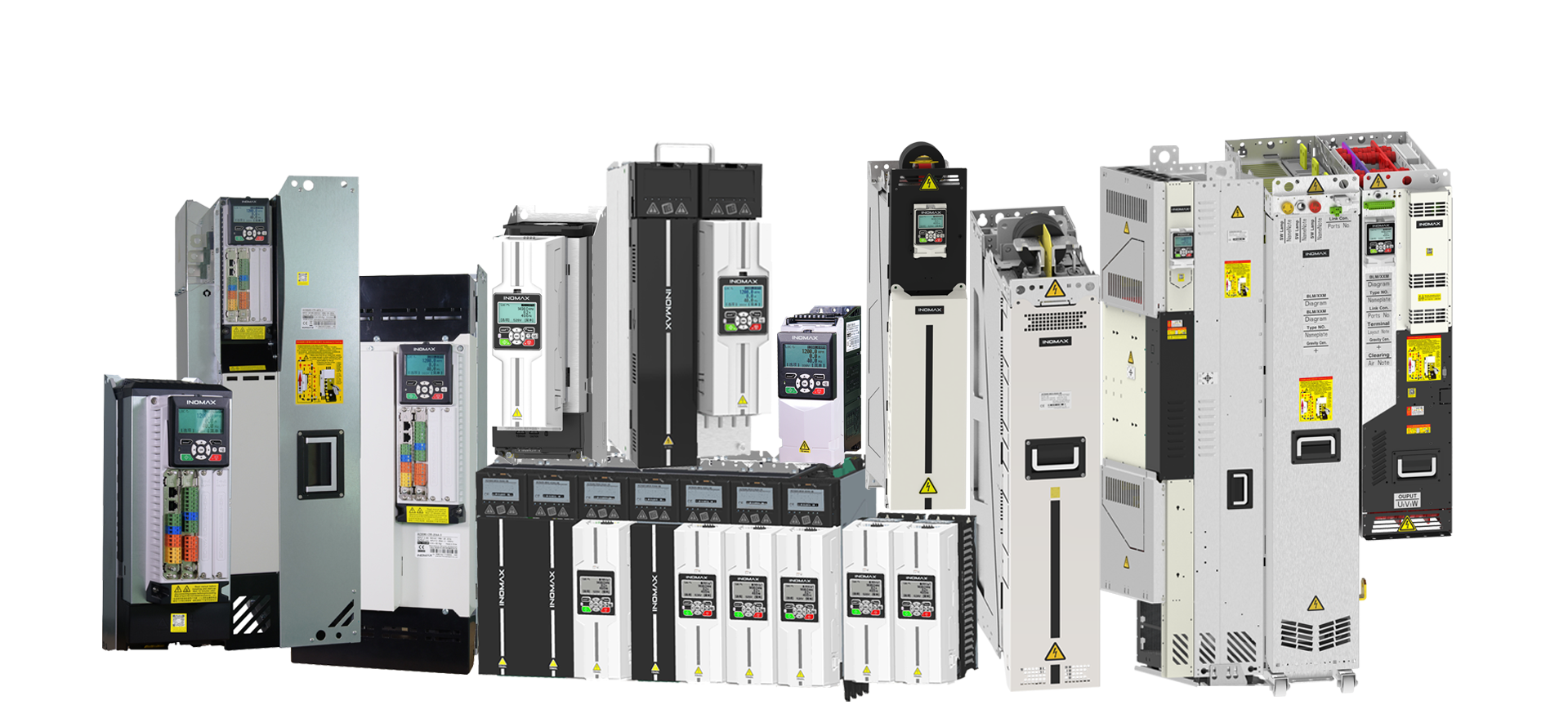
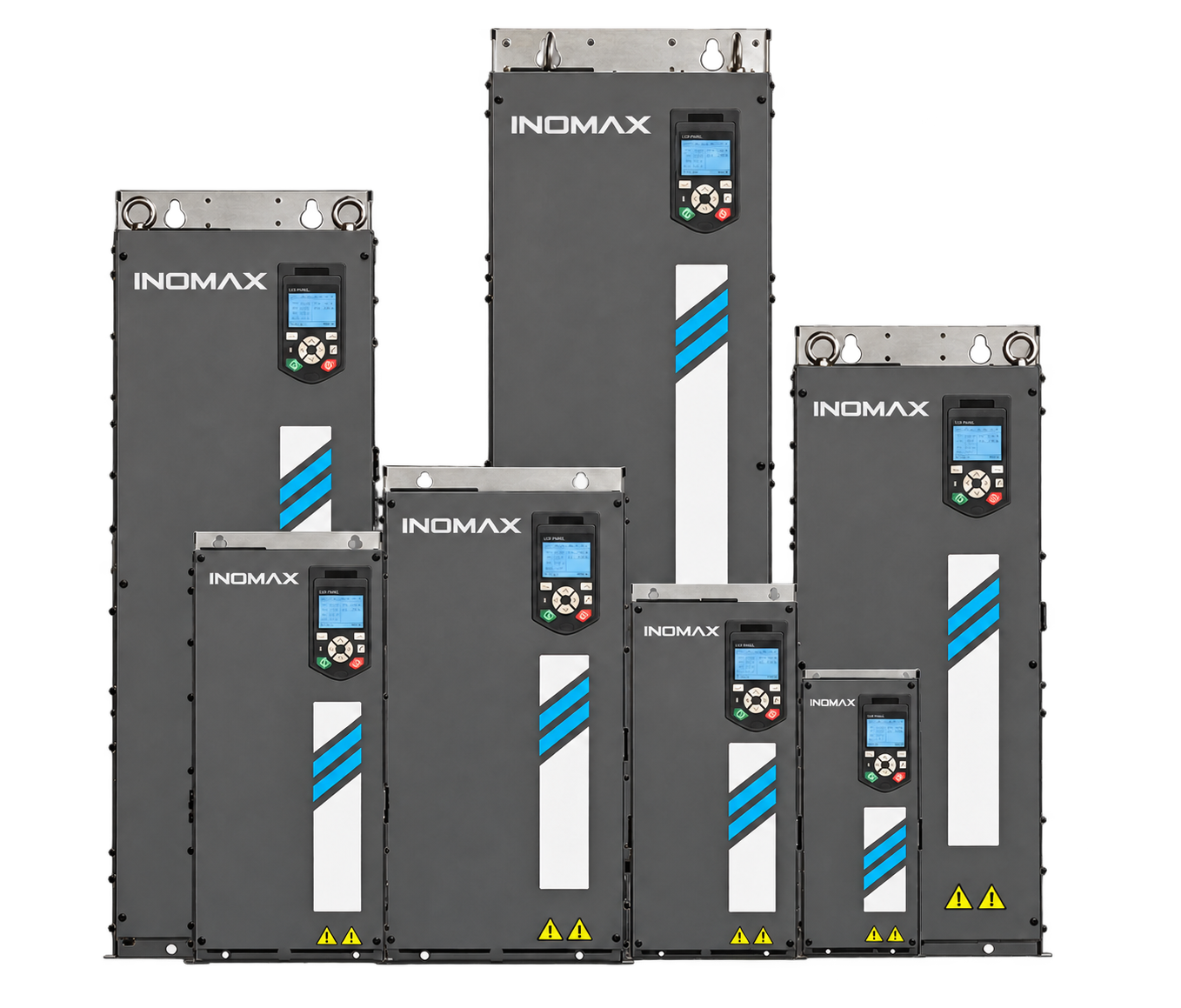
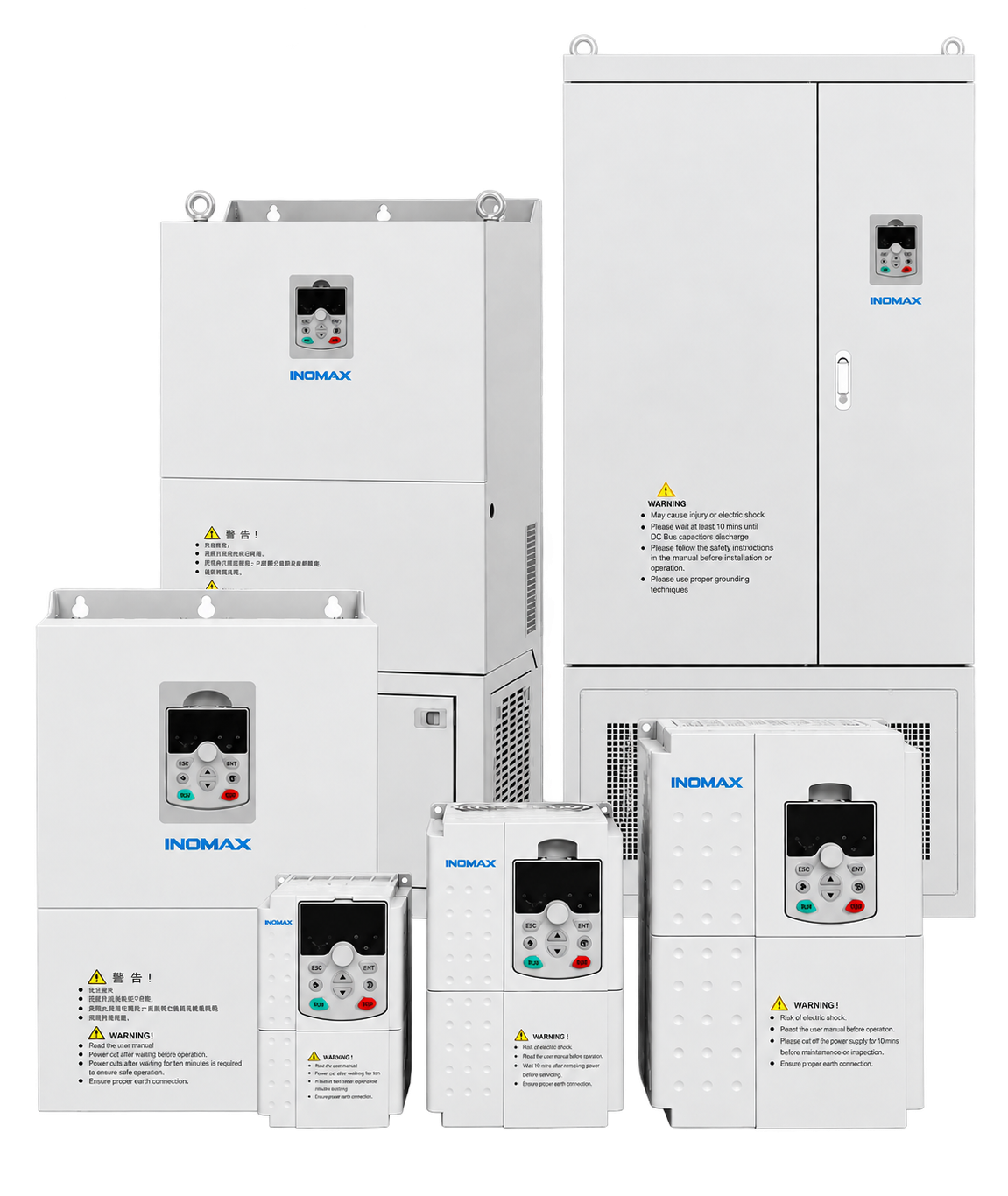
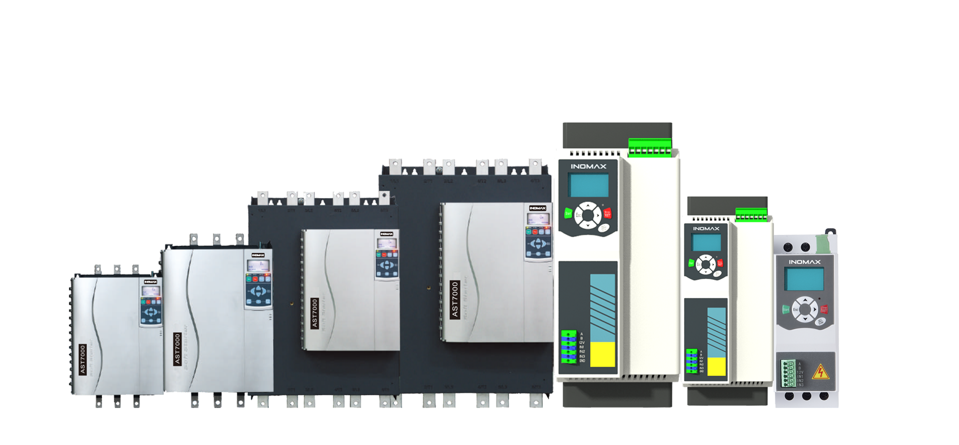




Scale the power stage
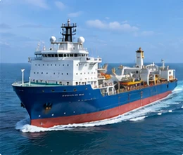
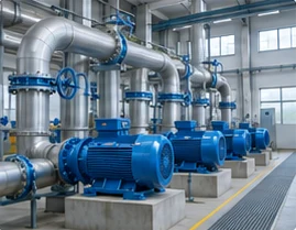
Parallel 1–16 suitable inverter or AFE modules. Liquid-cooled three-level 3.3 kV configurations support up to 4 MW per cabinet. Integrated drives and other topologies have different parallel-connection rules.

Modular drive systems / ACS890
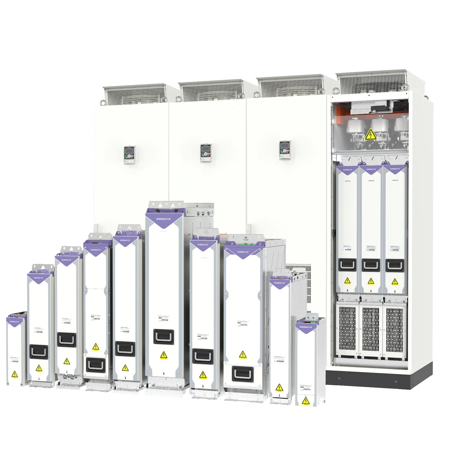
Build the power and control architecture your machine needs. Combine regenerative front ends, motor inverters and DC converters with advanced motor control, multi-motor coordination, and air- or liquid-cooled power units.
Explore the ACS890 range
Explore voltage-specific modules, power-system scaling, cooling and application configurations. Each product page includes selection data, accessories and answers to common engineering questions.
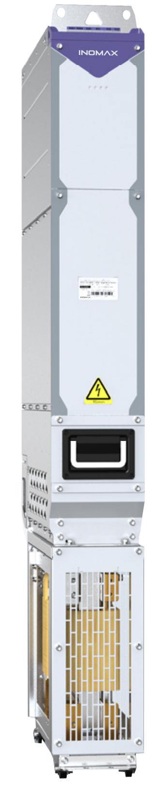 400V modulesACS890 400V Modular Drive SystemBuild a 400 V-class drive around the motor, load cycle and cabinet. ACS890 separates the control unit from inverter and supply modules, giving machine builders a practical route from a single controlled motor to an engineered common DC bus system.View product details →
 690V modulesACS890 690V Modular Drive SystemConfigure ACS890 for 690 V industrial motor systems using the catalog’s 700 V AC class and code -7 module families. Combine the selected inverter, front end, control and cooling arrangement around the duty of the machine.View product details →
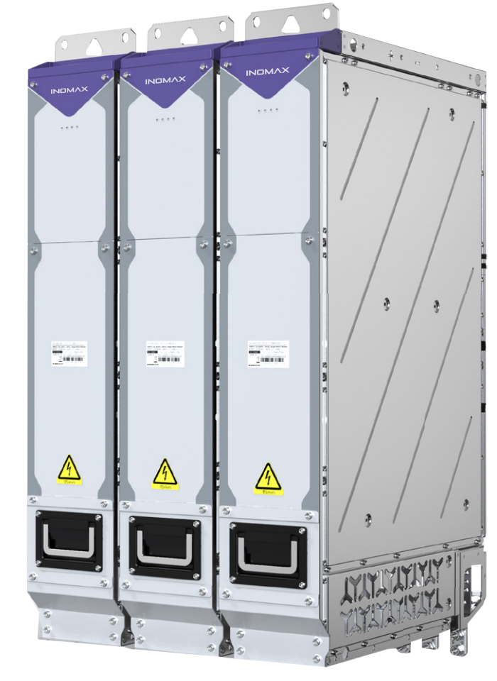 1140V liquid-cooledACS890 1140V Liquid-Cooled Drive SystemThe ACS890 1140 V liquid-cooled three-level platform is designed for engineered high-power motor systems. Select T-frame inverter modules together with the correct front end, cooling loop, precharge and control equipment.View product details →
 High-power parallelACS890 High-Power Parallel Drive SystemsScale the power stage around the required motor current and operating duty. ACS890 supports 1–16 eligible parallel inverter or AFE power units, with configuration-specific rules for current sharing, protection and cooling.View product details →
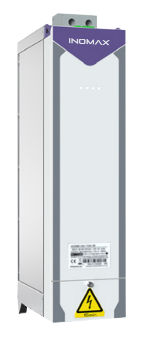 Air vs liquid coolingACS890 Air-Cooled and Liquid-Cooled VFDsChoose the cooling arrangement that fits the installation, then confirm the electrical rating. ACS890 offers air- and liquid-cooled platforms with different frame, voltage and current coverage.View product details →
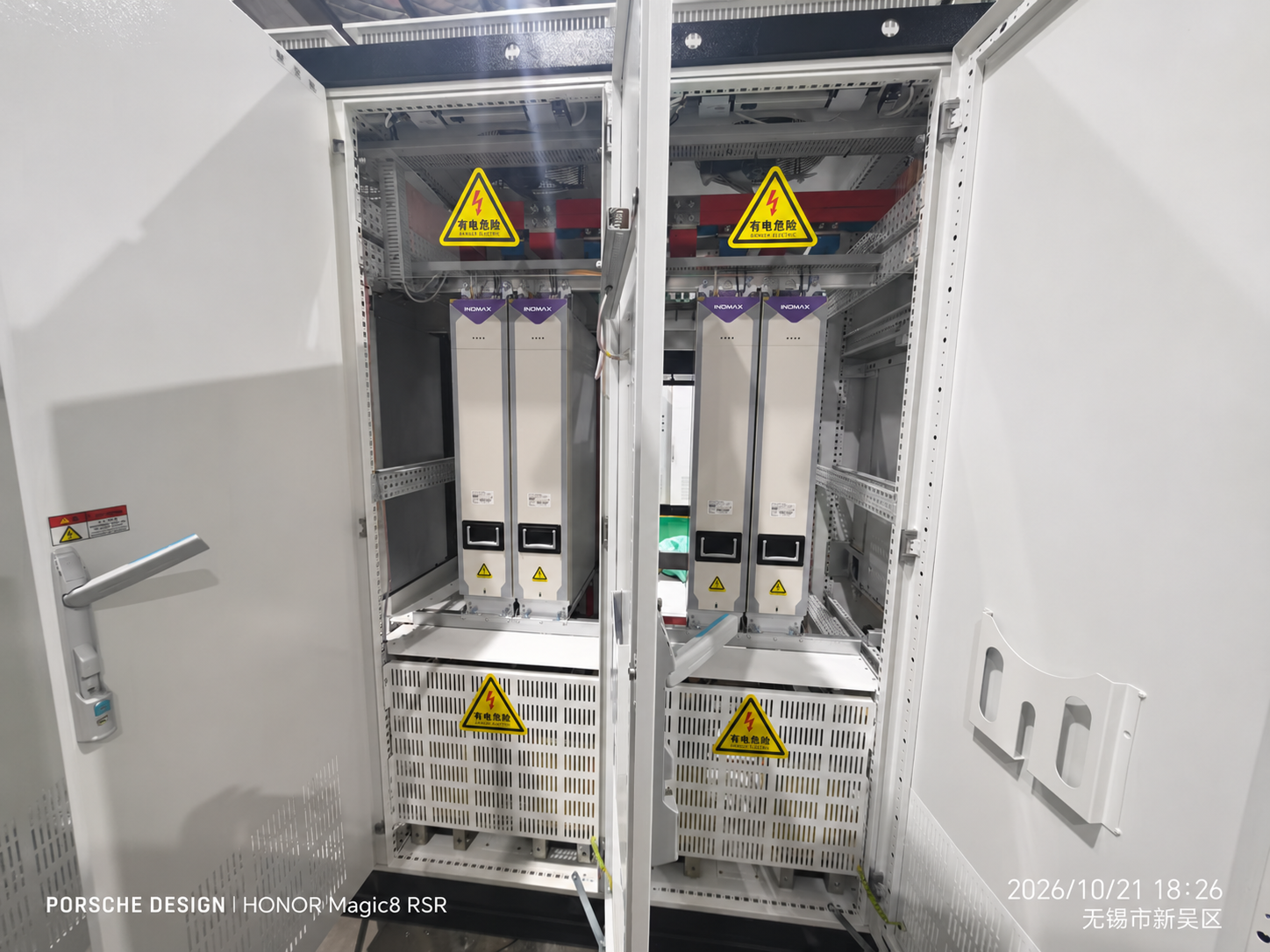 Regenerative AFEACS890 Regenerative AFE Drive SystemReturn usable braking energy through an engineered active front end. ACS890 ALM / AFE modules regulate the DC link and control grid current as part of a coordinated drive system.View product details →
 Common DC bus / multi-motorACS890 Common DC Bus and Multi-Motor DrivesCoordinate the motor group and manage energy across the machine. ACS890 combines a modular DC-link architecture with torque, speed and position-following functions for engineered multi-drive systems.View product details →
01 / Engineering platform
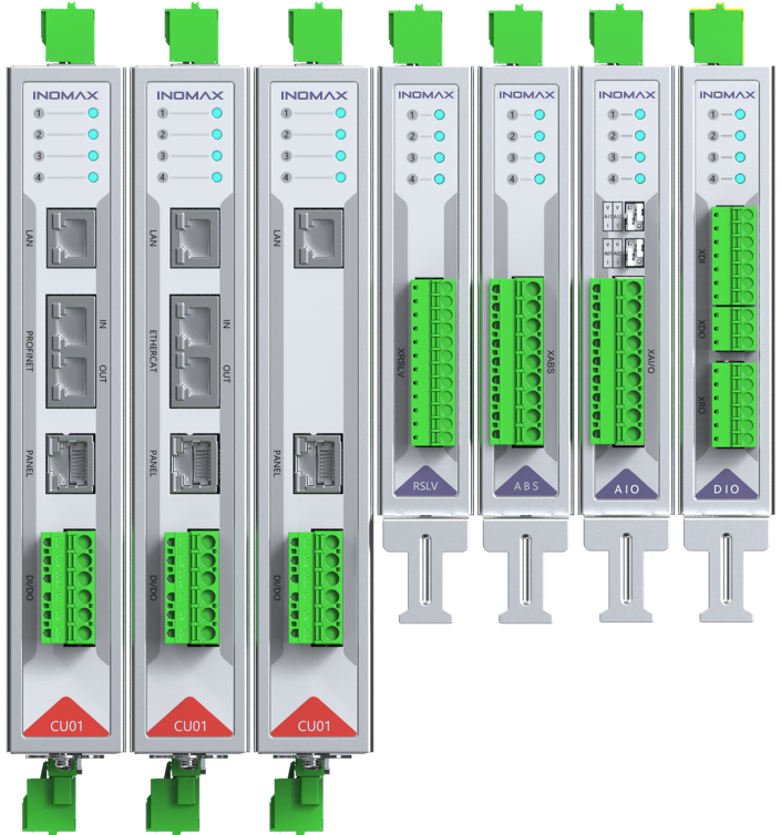
The ACS890 modular variable frequency drive separates control, feedback and power conversion. A control unit processes commands and measurements; FLYLINK synchronizes the connected modules; the selected power stages regulate energy between the grid, DC link and load.
Configure a common DC bus for multiple motors, an active front end for regenerative duties, or a DC/DC stage for controlled DC power. Select voltage class, current, overload duty and cooling around the actual application.
⇄
⇄
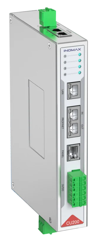
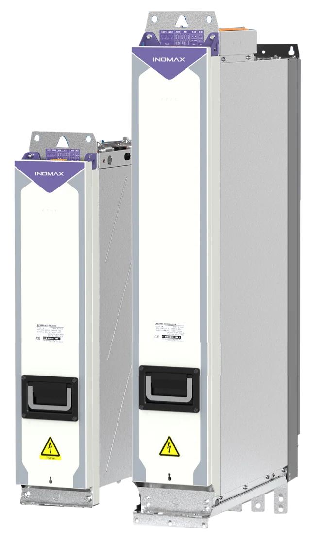
Dedicated control and power modules. Final assemblies depend on the selected configuration.
Parallel 1–16 suitable inverter or AFE modules. Liquid-cooled three-level 3.3 kV configurations support up to 4 MW per cabinet. Integrated drives and other topologies have different parallel-connection rules.
FLYLINK provides <10 ns inter-node clock difference and approximately 2.5 μs average node data exchange. Master-follower control supports speed, torque and position following for coordinated machines.
Support induction, permanent-magnet and other AC motor types, open- or closed-loop control, flying start and deep field weakening. Choose TTL, HTL, resolver, SinCos or absolute feedback to suit the machine.
¹ Parallel-unit count, 1–4 coordinated motors and 32 nodes per FLYLINK network are separate configuration limits. Timing specifications describe the network, not guaranteed mechanical synchronization accuracy. Interfaces depend on the control unit and extensions. Detailed tables below cover 400 / 700 / 900 / 1140 V AC classes and topology-specific DC voltages; 3.3 / 6 / 10 kV systems require project engineering.
02 / Advanced motor control
From identifying the motor to restarting a spinning load, ACS890 combines six control capabilities for demanding machinery. Match the control mode to the motor, mechanical coupling and operating duty.
At non-zero speed, ACS890 sensorless control is designed to approach encoder-based closed-loop performance. It optimizes motor current and excitation for the required load, helping reduce unnecessary current and associated losses.
Engineering valueConsider sensorless operation where installing and maintaining an encoder would add complexity. Select encoder feedback when the machine’s low-speed, positioning or dynamic requirements call for it.
Application fit Process drives, pumps, fans and retrofit evaluations.
Identify the electrical and mechanical parameters used by the control model, with separate routines for a stationary motor and a motor that can rotate.
Stator resistance, induction-motor inductance, d/q-axis inductances and encoder electrical position.
Back-EMF constant, induction-motor magnetizing current, mechanical inertia, and encoder phase / resolution.
Engineering valueBuild a motor-specific basis for commissioning and tuning. Choose the identification routine around the motor type and whether the connected machine can be run during commissioning.
Application fit Motor replacement, machine commissioning and drive retrofits.
Maintain full-voltage output with minimum field-weakening current and near-constant-power capability. Dynamic compensation tracks the voltage limit to sustain the maximum power available within the motor and drive limits.
Engineering valueUseful when the machine needs an extended constant-power speed range. Available torque falls as speed rises above base speed, so check the complete load envelope during selection.
Application fit Spindles, coilers and variable-speed test systems.
Engineering valueSelect the following mode according to the mechanical relationship between axes. Configurable Ethernet data mapping supports the exchange of the variables required by the machine.
Application fit Coupled drives, coordinated rolls, winding and position-following machinery.
Engineering valueCoordinate the motor group around the load instead of treating each drive independently. The catalog specifies 1–4 coordinated motors; this is separate from the 1–16 parallel power-unit limit.
Application fit Conveyors, tunnel boring, traction and flywheel systems.
Detect an already-spinning load in open- or closed-loop operation without an auxiliary speed sensor, then transition into the selected control mode.
For induction motors, search is followed by rapid excitation. For PMSMs, automatic detection avoids a search delay at standstill.
Engineering valueResume control of loads that are still moving, for example a coasting fan. The figures above describe the catalog search stage, not the total restart or acceleration time.
Application fit Coasting fans, pumps and other rotating-load restart duties.
Share the motor type, speed range, feedback device, mechanical coupling and operating cycle. INOMAX can review the control and power configuration together.
03 / Integration & commissioning
A 64-bit floating-point multicore CPU and FPGA support motor calculations, parallel feedback processing and real-time drive functions. Configure the feedback and communications around your existing machine architecture.
Motor & feedback flexibility
Control squirrel-cage and wound-rotor induction motors, surface-mounted and interior PMSMs, PM-assisted synchronous reluctance motors, and electrically excited synchronous motors. The platform also covers linear, disc-rotor and 6-, 9- or 12-phase machines in the applicable configuration.
Multiple encoder interfaces can operate together. Adapter, cable and motor-speed limits must be checked for the selected feedback configuration.
Commissioning & diagnostics
Engineering valueCompare current, speed and other recorded variables across the operating cycle to support tuning, commissioning and fault investigation.
FLYLINK synchronizes the power platform. The 100 Mbps network provides <10 ns inter-node clock difference and approximately 2.5 μs average node data exchange. Daisy-chain connections identify and compensate for cable delay automatically. CU200 supports two independent networks, each with up to 32 nodes; either can be assigned as the main network.
Ethernet supports drive-to-drive coordination. The commissioning Ethernet port can also exchange speed, torque and position references through a switch. Multiple masters and followers, simultaneous broadcast reception and configurable data frames support machine-specific coordination. Typical independently configured cycles are 0.25 ms, 1 ms and 10 ms.
FLYLINK clock difference and Ethernet update cycles are communication specifications. Mechanical accuracy also depends on the motor, feedback, load and control tuning.
PLC interfaces: PROFINET RT / IRT, EtherCAT, EtherNet/IP, CANopen, Modbus TCP and Modbus RTU are listed for the platform; PROFIBUS DP is available through expansion. Confirm the required protocol with the selected control unit and interface option.
Digital expansion: 6 DI, 2 PNP DO and 2 relay outputs per module, with a 250 μs refresh interval and up to 5 modules per network. Analog expansion: 2 differential AI and 2 single-ended AO per module, with a 250 μs refresh interval and up to 2 modules per network.
Grid feedback: AC sensing measures three-phase voltage and current, calculates active and reactive power, and supports phase locking and fault detection. DC sensing measures up to 2,000 V directly, with an external voltage-reduction module for higher ranges. AC and DC grid modules specify a 250 μs period / latency.
Motor-drive hardware: the catalog lists STO, PT100 / KTY84 load-temperature feedback and three-phase current measurement. Inverter modules and integrated drives also provide output ground-fault protection. Confirm the applicable hardware functions and safety documentation for the proposed system.
Local operation: the CP68 industrial 128 × 64 LCD panel supports Chinese and English text, status monitoring, event-log review and parameter reading / writing. Door mounting and an optional CPSP quick-release bracket support cabinet integration.
Cooling and installation: select air or liquid cooling by voltage class and frame. Final sizing must account for motor current, overload duty, ambient conditions and the cabinet’s heat-removal arrangement.
04 / System architecture
Select a module to see its role and example model families. The diagram shows functional paths around a shared DC link.
Swipe the diagram horizontally to explore the full system. Select a module above for its details.
ALM / AFE regulates DC voltage and grid current, with voltage boost / buck functions and constant-voltage / constant-power modes. For regenerative duties, define the returned power and duty cycle together with the filter, precharge and grid-feedback arrangement.
A common DC bus connects motor and power-conversion branches in one coordinated architecture. DCDC stages provide constant output voltage, current or power, plus input-voltage control. The non-isolated design shares DC negative; load-side paralleling requires the specified DC LC filters.
CHG active precharge uses phase-controlled SCRs without a precharge resistor, with self-adjusting timing and contactor sequencing. BRK modules control the braking-resistor path, support star / delta resistor connections and specify <20 μs voltage-loop response. Select resistor resistance and thermal duty for the load cycle; direct BRK paralleling is prohibited.
Functional architecture, not installation wiring. The regenerative front end requires the matched filter, precharge and feedback arrangement. BLM + AC reactor and SLM + AC reactor + CHG are alternative front-end configurations; their parallel-connection rules differ.
05 / Engineering selection
Compare 148 catalog power-module entries. Build a shortlist for engineering review; current, overload duty and operating conditions determine the final selection.
| Model / voltage class | PN (kW) | Current (A) | W × D × H (mm) | Weight (kg) | Shortlist |
|---|---|---|---|---|---|
| 400 V AC · Air · INV | 15 | 32IN (A) | 86×230×290 | 3.1 | |
| 400 V AC · Air · INV | 18.5 | 38IN (A) | 86×230×290 | 3.1 | |
| 400 V AC · Air · INV | 22 | 45IN (A) | 86×230×290 | 3.1 | |
| 400 V AC · Air · INV | 30 | 61IN (A) | 86×230×290 | 3.1 | |
| 400 V AC · Air · INV | 37 | 72IN (A) | 125×265×540 | 11 | |
| 400 V AC · Air · INV | 45 | 87IN (A) | 125×265×540 | 11 | |
| 400 V AC · Air · INV | 55 | 115IN (A) | 125×265×540 | 11 | |
| 400 V AC · Air · INV | 75 | 145IN (A) | 125×265×540 | 12 | |
| 400 V AC · Air · INV | 90 | 182IN (A) | 125×265×540 | 12 | |
| 400 V AC · Air · INV | 110 | 226IN (A) | 125×380×635 | 20 | |
| 400 V AC · Air · INV | 132 | 246IN (A) | 125×380×635 | 20 | |
| 400 V AC · Air · INV | 160 | 293IN (A) | 170×460×800 | 40 | |
| 400 V AC · Air · INV | 200 | 363IN (A) | 170×460×800 | 40 | |
| 400 V AC · Air · INV | 250 | 487IN (A) | 170×460×800 | 40 | |
| 400 V AC · Air · INV | 280 | 546IN (A) | 170×460×800 | 40 | |
| 400 V AC · Air · INV | 315 | 624IN (A) | 170×585×980 | 73 | |
| 400 V AC · Air · INV | 355 | 674IN (A) | 170×585×980 | 73 | |
| 400 V AC · Air · INV | 400 | 760IN (A) | 170×585×980 | 73 | |
| 400 V AC · Air · INV | 450 | 865IN (A) | 170×585×980 | 73 | |
| 400 V AC · Air · INV | 500 | 915IN (A) | 170×585×980 | 73 | |
| 700 V AC · Air · INV | 132 | 142IN (A) | 125×380×635 | 20 | |
| 700 V AC · Air · INV | 160 | 175IN (A) | 125×380×635 | 20 | |
| 700 V AC · Air · INV | 200 | 210IN (A) | 125×380×635 | 20 | |
| 700 V AC · Air · INV | 250 | 271IN (A) | 125×460×800 | 31 | |
| 700 V AC · Air · INV | 280 | 300IN (A) | 125×460×800 | 31 | |
| 700 V AC · Air · INV | 315 | 330IN (A) | 125×460×800 | 31 | |
| 700 V AC · Air · INV | 355 | 370IN (A) | 125×460×800 | 31 | |
| 700 V AC · Air · INV | 400 | 430IN (A) | 170×585×980 | 75 | |
| 700 V AC · Air · INV | 450 | 470IN (A) | 170×585×980 | 75 | |
| 700 V AC · Air · INV | 500 | 522IN (A) | 170×585×980 | 75 | |
| 700 V AC · Air · INV | 560 | 590IN (A) | 170×585×980 | 75 | |
| 400 V AC · Liquid · INV | 400 | 760IN (A) | 170×510×930 | 55 | |
| 400 V AC · Liquid · INV | 500 | 915IN (A) | 170×510×930 | 55 | |
| 700 V AC · Liquid · INV | 560 | 590IN (A) | 170×510×930 | 55 | |
| 700 V AC · Liquid · INV | 630 | 640IN (A) | 170×510×930 | 55 | |
| 700 V AC · Liquid · INV | 710 | 720IN (A) | 170×510×930 | 55 | |
| 700 V AC · Liquid · INV | 800 | 780IN (A) | 170×510×930 | 55 | |
| 900 V AC · Liquid · INV | 500 | 401IN (A) | 170×595×1110 | 80 | |
| 900 V AC · Liquid · INV | 700 | 561IN (A) | 170×595×1110 | 80 | |
| 900 V AC · Liquid · INV | 500 | 401IN (A) | 170×510×930 | 51 | |
| 900 V AC · Liquid · INV | 700 | 561IN (A) | 170×510×930 | 51 | |
| 900 V AC · Liquid · INV | 800 | 642IN (A) | 170×545×1090 | 75 | |
| 900 V AC · Liquid · INV | 1000 | 802IN (A) | 170×545×1090 | 75 | |
| 900 V AC · Liquid · INV | 1400 | 1123IN (A) | 170×545×1090 | 75 | |
| 900 V AC · Liquid · INV | 1600 | 1283IN (A) | 240×630×1260 | 130 | |
| 1140 V AC · Liquid · INV | 500 | 317IN (A) | 170×595×1110 | 80 | |
| 1140 V AC · Liquid · INV | 650 | 412IN (A) | 170×595×1110 | 80 | |
| 1140 V AC · Liquid · INV | 500 | 317IN (A) | 170×510×930 | 51 | |
| 1140 V AC · Liquid · INV | 650 | 412IN (A) | 170×510×930 | 51 | |
| 1140 V AC · Liquid · INV | 1000 | 633IN (A) | 170×545×1090 | 75 | |
| 1140 V AC · Liquid · INV | 1300 | 823IN (A) | 170×545×1090 | 75 | |
| 1140 V AC · Liquid · INV | 1500 | 950IN (A) | 240×630×1260 | 130 |
Read the rating correctly. INV: motor current IN. AFE / SLM / BLM: AC / DC currents. DC/DC: mean total DC output current. BRK: mean output phase current. DC input and braking-bus ratings are kept separate from AC voltage classes. The catalog’s 700 V AC class includes code -7 / 690 V applications; verify the operating range.
Duty and conditions. Click a model for its light- and heavy-duty values, where provided. PN is a catalog reference, not a substitute for current sizing. For applicable parallel systems, the catalog uses 0.97 × module count × rated current. Apply topology rules and thermal derating. Dimensions are module dimensions, not cabinet dimensions.
Need 3.3 kV, 6 kV or 10 kV? Request a configured system → These architectures are engineered by project and are not represented as standard low-voltage module rows.
06 / Application engineering
Explore an ACS890 engineering proposal and related INOMAX project experience. Each reference identifies its platform and application scope.
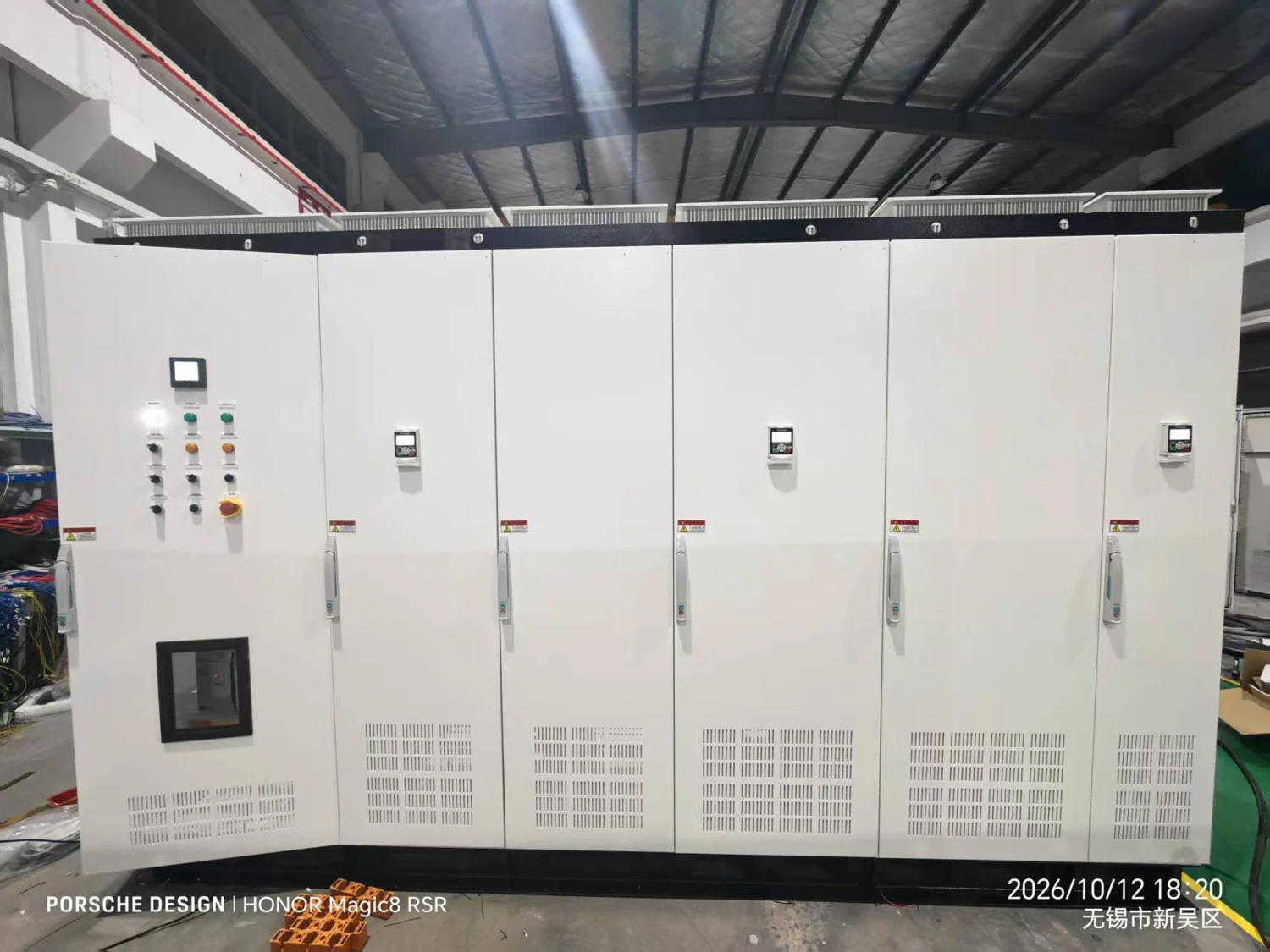
Three-level liquid-cooled conversion for a high-speed PM generator and a 690 V grid connection. The project selection duty is up to 2.5 MW; generator nameplate power is 3 MW.
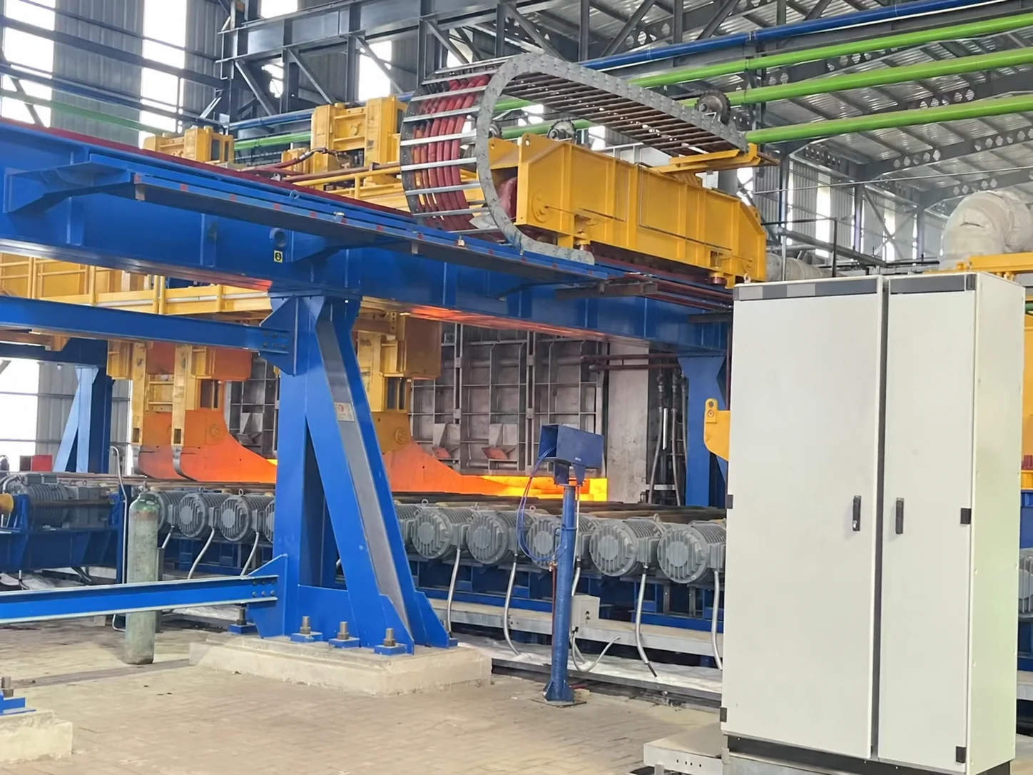
Regenerative drive engineering for multi-motor roller conveyors and DC-to-AC modernization. A useful reference for power architecture, load sharing and coordinated drive integration.
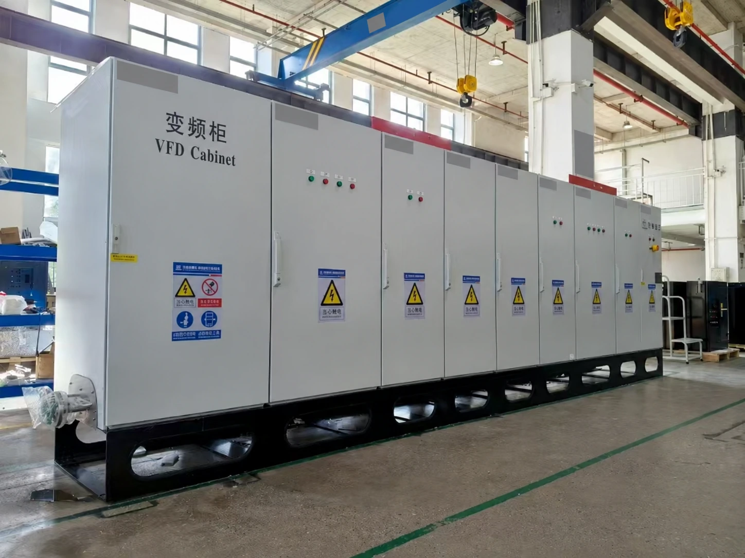
Project-specific liquid-cooled AFE cabinets for NN Leonis propulsion and thruster applications. The ACS880 reference illustrates INOMAX’s retrofit and interface-matching experience.
Rolling mills, coilers and shears: align torque, speed and position duties with a shared DC bus and a suitable regenerative front end.
Electric propulsion, winches and deck machinery: specify cooling, interfaces and the approval scope for the vessel’s requirements.
Main cutterheads, segment handling and conveyors: coordinate motors sharing a load and size the system for the starting and overload duty.
Motor and drivetrain testing: combine motor control, energy regeneration, encoder feedback and waveform capture for the test cycle.
07 / Engineering resources
Get the full catalog or request documents matched to the module, cabinet and approval requirements of your project.
Architecture, interfaces, model codes and detailed selection tables.
English · PDF · 42 pages · 10 MB
Request the manual for your selected module.
Specify modules or a complete cabinet assembly.
Model-specific conformity and project requirements.
Cabinet space, energy flow and selection checklist · PDF
Company credentials, with model-specific scope. The catalog lists ISO 9001, ISO 14001, ISO 45001, CE/LVD, CE/EMC, EAC, CCS and RS. Product approval applies only to the models and conditions stated in the relevant certificate. Request the applicable documents for your project.
08 / Before you specify
Explore where ACS890 fits, how it compares with your existing drive system, and what to expect from selection, production and after-sales support.
ACS890 is designed for demanding industrial systems that need flexible power conversion and coordinated motor control. Typical applications include rolling mills, coilers and shears; marine propulsion, winches and deck machinery; tunnel-boring cutterheads and conveyors; oil and gas drilling; and motor or drivetrain test benches.
It also supports precision machine tools, paper and web-handling lines, rubber and plastics machinery, flywheel energy storage and other engineered energy-conversion systems. The power stage, motor-control mode and cooling arrangement are selected for the actual operating cycle.
Yes. ACS890 can be engineered as an alternative to ABB, Siemens or VACON drive systems in suitable high-power, regenerative, common-DC-bus and multi-motor applications. INOMAX has experience with industrial projects replacing established drive brands.
For a retrofit, send the existing drive model, motor nameplate and basic application requirements. We review current and overload ratings, supply and DC-link voltages, PLC communication, encoder feedback, cooling and cabinet space, then propose the ACS890 configuration and required installation changes. Replacement is evaluated at system level; matching the kW rating alone is not sufficient.
A conventional standalone VFD combines most drive functions in one unit. ACS890 separates the control unit, feedback interfaces and power modules, allowing the system designer to choose motor inverters, rectifiers, active front ends, DC/DC converters and braking units around a shared architecture.
This is useful when a project needs a common DC bus, energy regeneration, several coordinated motors, parallel power modules or a custom cabinet arrangement. It lets the power and control configuration follow the machine's requirements.
Key functions include sensorless control, standstill and rotating motor identification, deep field weakening, torque/speed/position master-follower control, multi-motor coordination and flying start. These functions address motor tuning, extended speed ranges, load sharing and restarting an already-spinning load.
FLYLINK specifies less than 10 ns inter-node clock difference and approximately 2.5 μs average node data exchange. Flying-start search is approximately 30 ms for induction motors and 5 ms for PMSMs. These are network and search-stage figures; final machine performance depends on the motor, feedback, load and commissioning.
The catalog includes 400 V and 700 V AC-class platforms, with three-level liquid-cooled configurations at 900 V and 1140 V. The 700 V class includes code -7 / 690 V applications. Project-engineered systems also cover 3.3 kV, 6 kV and 10 kV architectures.
Power depends on the module, voltage, cooling and permitted parallel arrangement. The catalog's up-to-4-MW-per-cabinet figure specifically applies to its 3.3 kV liquid-cooled three-level configuration. Use the module selector for individual ratings, then size the complete drive by motor current, overload duty and operating conditions.
ACS890 supports squirrel-cage and wound-rotor induction motors, surface-mounted and interior permanent-magnet synchronous motors, PM-assisted synchronous reluctance motors and electrically excited synchronous motors. Applicable configurations also cover linear motors, disc-rotor motors and 6-, 9- or 12-phase machines.
Open-loop or closed-loop operation is selected for the duty. TTL, HTL, resolver, SinCos and absolute-encoder interfaces provide feedback options for applications with demanding speed, torque or positioning requirements.
Yes. A suitable ALM / active front end enables controlled energy flow between the AC supply and DC link, including returning regenerated energy to the grid. A common DC bus connects the selected motor and power-conversion branches within one coordinated system.
This architecture is relevant to test benches, coilers, hoisting, marine and energy-conversion duties. The design includes the appropriate grid filter, precharge and feedback arrangement. Where energy is dissipated in resistors, a BRK module and resistor bank are sized for the braking power and thermal duty.
Yes. The catalog specifies 1–4 coordinated motors and 1–16 suitable inverter or AFE power units in parallel. These are separate limits: paralleling modules increases the power stage, while multi-motor control coordinates the loads. Master-follower functions support torque sharing and speed or position following.
Parallel rules depend on the topology. Integrated drives do not support module paralleling; BLM/SLM require individual AC reactors, DC/DC requires the specified DC LC filters, and direct paralleling of braking modules is prohibited. INOMAX reviews the complete arrangement during selection.
Choose air cooling when the cabinet layout and ventilation can remove the required heat and the installation benefits from an air-cooled arrangement. Consider liquid cooling for high-power systems where cabinet space, heat removal or the existing cooling infrastructure makes it appropriate, including marine and large industrial installations.
Availability depends on voltage class and frame. For liquid-cooled selection, provide the coolant conditions and available heat-rejection capacity; for air-cooled selection, provide ambient temperature and cabinet ventilation conditions.
The platform lists PROFINET RT / IRT, EtherCAT, EtherNet/IP, CANopen, Modbus TCP and Modbus RTU, with PROFIBUS DP through expansion. Protocol availability depends on the selected control unit and interface option. Digital and analog I/O expansion, encoder adapters and AC/DC grid-sensing modules support machine integration.
Commissioning through Ethernet supports several control units from one PC. The diagnostic functions record 12 waveform channels at 4,000 samples per second, replay recordings, compare drives on one time axis and compare parameter settings online or offline. Wi-Fi and remote access use a configured router or gateway.
Standard module orders and complete custom cabinets are scheduled separately. Module availability, order quantity, cooling equipment, cabinet assembly and factory testing all affect the manufacturing period; the current ACS890 schedule is confirmed with the selected configuration and technical approval.
For reference, previous INOMAX project schedules include approximately two weeks for a regenerative-drive project and a quoted 4–6 weeks for liquid-cooled marine cabinets. These are project references, not a fixed lead time for every ACS890 order. Send your required delivery or shutdown date so we can propose a production schedule; transport time is quoted separately.
INOMAX provides a standard two-year warranty. The quotation and order documents state the warranty start date, coverage and service arrangements for the supplied ACS890 modules or cabinet system.
Our technical team supports troubleshooting and remote diagnosis. For large systems, the project can also define a spare-parts package and service plan to support maintenance and reduce downtime.
Yes. INOMAX can work with system integrators, equipment manufacturers and project contractors on module selection, complete cabinet configurations and OEM requirements. The scope can include power conversion, cooling, reactors or filters, precharge, braking, control interfaces and enclosure requirements.
Specify whether you need modules for your own cabinet design or an assembled drive system. We then define the electrical and mechanical interfaces, documentation, testing and delivery scope for the project.
INOMAX provides application selection support, technical clarification and remote commissioning assistance. Our team can help review the motor data, power architecture, PLC and encoder interfaces, parameter settings and operating waveforms.
On-site commissioning, training and spare-parts arrangements can be discussed for the project and included in the agreed service scope. Send the application requirements early so the drive configuration and support plan can be developed together.
Yes. The full ACS890 catalog is available through this page. Request hardware manuals, installation dimensions, CAD / STEP drawings and applicable certificate documents against your selected module or cabinet configuration.
For marine projects, tell us the required classification society and approval scope. The catalog lists CCS and RS among company credentials; the supplied product's certification must match the models and conditions stated in the relevant certificate.
Start with the application, supply voltage, motor nameplate, motor quantity and required speed range. Add the overload or operating cycle, whether regeneration is required, the cooling preference and the PLC or encoder interface if known.
For a replacement, include the existing drive model and photos of the nameplate and cabinet. You can use the module selector to build a shortlist, but it is not necessary to choose a final model before contacting INOMAX. Our engineering team can recommend the configuration from your project requirements.
Partner support, test-unit terms and project scope are agreed case by case.
09 / Start your project
Tell us what the machine needs to do. Share the supply voltage, motor current and power, operating cycle, cooling preference and integration requirements.
Partner with INOMAX for your next high-power drive project.
Include your company, motor ratings, voltage, cooling, PLC interfaces and required delivery date. Your module shortlist is included automatically.
INOMAX uses your details to respond to this inquiry. You can also email info@inomaxtechnology.com.