



VFD Knowledge: Working Principles, Voltage Ratings and Industrial Applications
A practical guide to variable frequency drives. Understand what a VFD does, how it controls a motor, where it is used and which electrical and mechanical requirements determine the right configuration.
What Is a Variable Frequency Drive?
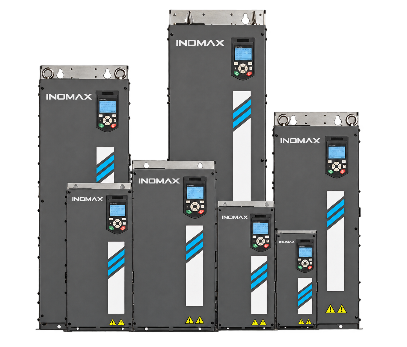
A variable frequency drive (VFD) is an electronic motor controller that adjusts the frequency and voltage supplied to a compatible AC motor. By controlling the electrical supply, it allows a machine to operate at a suitable speed instead of running continuously at one fixed speed. Depending on the drive and control method, it can also regulate torque and respond to changes in mechanical load.
In industry, closely related names include AC drive, frequency inverter, frequency converter and adjustable frequency drive. Variable speed drive (VSD) is a broader term that can include other speed-control technologies. When specifying equipment, the important question is what motor and process the controller must operate, rather than which name appears on the enquiry.
A VFD is used as part of a complete drive system: electrical supply, drive, motor, transmission and driven machine. Its performance depends on all of these elements. A well-selected drive cannot compensate for an unsuitable motor, an overloaded gearbox or a pump operating outside its permitted range.
How Does a VFD Work?
A common voltage-source AC drive has three main power stages. The rectifier converts the incoming AC supply into DC. The DC link provides an intermediate energy-storage and smoothing stage. The inverter switches this DC supply to produce the controlled output needed by the motor. A control board coordinates the power devices using measurements, motor settings and the operating command.
Rectifier and input stage
Many drives use a diode rectifier for normal motoring operation. An active front end (AFE) uses controlled power devices and a suitable input filter. In an appropriately engineered system, an AFE supports returning energy to the supply and controlling input-current quality. These capabilities depend on the actual configuration; they are not standard features of every VFD.
DC link and inverter stage
The DC link connects the input and output conversion stages. The inverter commonly uses insulated-gate bipolar transistors (IGBTs) with pulse-width modulation (PWM). The switching pattern establishes the motor’s effective voltage and fundamental frequency. The motor terminal voltage is a pulse waveform, not the same waveform as the utility supply, which is why motor insulation, cable length and output filtering deserve attention.
Control and feedback
The controller receives a speed or torque request from a keypad, analog signal, digital input or industrial network. It measures relevant electrical quantities and adjusts the output. Encoder feedback can be added where the selected control scheme requires accurate speed information, low-speed performance or position-related functions.
How Does Frequency Affect Motor Speed?
For an AC motor, the speed of the rotating magnetic field depends on electrical frequency and the number of poles. Synchronous speed in revolutions per minute is calculated as 120 × frequency in Hz ÷ number of poles. A four-pole motor therefore has a synchronous speed of 1,500 rpm at 50 Hz and 1,800 rpm at 60 Hz.
An induction motor normally runs slightly below synchronous speed while producing motoring torque; this difference is called slip. A synchronous motor follows the rotating field when operating in synchronism. Actual shaft-speed requirements must therefore be evaluated with the motor type and control method.
Increasing the frequency is not permission to run any motor faster. Mechanical speed limits, bearings, rotor strength, connected equipment and the motor’s electrical limits must all be checked. Above the base-speed region, available voltage can limit the flux and torque. At low speed, a shaft-mounted cooling fan may provide insufficient cooling even though the motor is developing substantial torque.
VFD Voltage Ratings: 230 V, 400 V, 480 V, 690 V and Medium Voltage
A VFD must match both the electrical supply and the motor. Input voltage, permissible supply variation, phase count, output voltage and the motor winding connection are separate checks. Selecting only by kW or horsepower can result in an incompatible system.
| Typical voltage class | Where it may be encountered | What to verify |
|---|---|---|
| 200–240 V | Smaller machines and equipment supplied from suitable single-phase or three-phase circuits | Exact input phase configuration, output phase configuration and motor connection |
| 380–415 V | Industrial machinery, pumping systems, ventilation and process equipment | Actual site voltage, motor rated current and applicable supply tolerance |
| 440–480 V | Industrial installations using these supply voltages | Drive voltage class, insulation requirements and regional electrical design |
| 600–690 V | Some high-power industrial, marine and mining systems | Motor and drive ratings, switchgear, cooling and complete cabinet design |
| 1,140 V project systems | Special industrial or mining applications | A dedicated compatible configuration; do not treat it as an ordinary 690 V drive |
| 3.3 kV, 4.16 kV, 6 kV, 6.6 kV and other medium-voltage systems | Larger motors and plant-specific electrical networks | Converter topology, transformer arrangement, insulation, protection and project engineering |
These are examples of industry voltage classes, not a claim that every INOMAX model covers every voltage listed. Confirm availability against the selected product documentation. A standard 400 V-class drive should not be assumed to produce a 690 V motor supply. Likewise, single-phase input does not mean single-phase motor output: many small drives accept single-phase power and supply a compatible three-phase motor.
Where Are Variable Frequency Drives Used?
VFD applications range from building services to heavy industrial production. The reason for using a drive varies: energy control, accurate process speed, coordinated motion, controlled acceleration or recovery of braking energy. The application determines which functions matter most.
| Industry or equipment | Purpose of VFD control | Important engineering checks |
|---|---|---|
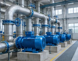
| Water supply and wastewater treatment | Regulate pump speed to meet changing flow or pressure requirements | Pump curve, minimum flow, operating head, motor cable and process protection |
| HVAC and ventilation | Adjust fan or circulation-pump output to building demand | Control signals, resonance, low-speed operation and acoustic requirements |
| Conveyors and material handling | Control line speed and acceleration under changing load | Starting torque, load sharing, overload and stopping behaviour |
| Cranes, hoists and winches | Control lifting and lowering with coordinated braking | Low-speed torque, feedback, regenerative duty and mechanical-brake sequence |
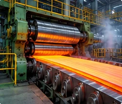
| Steel mills and rolling lines | Coordinate roller tables, process equipment and reversing motion | Dynamic torque, repeated acceleration, multiple motors and energy flow |
| Paper, film and winding machines | Control line speed and tension through changing roll diameter | Tension feedback, torque range, synchronization and braking duty |
| Mining, cement and bulk materials | Operate conveyors, fans, crushers and other large machinery | Heavy-load starts, dust, ambient conditions and overload duration |
| Compressors and process machinery | Match output to process requirements | Permitted speed range, lubrication, cooling and machine-specific restrictions |
| Marine propulsion auxiliaries and thrusters | Control motor speed and torque in vessel systems | Cooling utilities, space, supply quality and project certification requirements |
| Motor test benches and high-speed motors | Reproduce defined speed and load operating points | Electrical frequency, motor parameters, feedback, current and regenerative capability |
For example, a ventilation fan may mainly need stable speed control and efficient part-load operation. A mine hoist also needs reliable torque during lifting, a defined brake-control sequence and management of energy during lowering. These machines may use the same general drive technology but require very different configurations.
How Can a VFD Reduce Energy Consumption?
Energy savings arise when controlling motor speed improves the way the process operates. For a centrifugal fan or pump in a suitable system, reducing speed can reduce the power required instead of wasting energy across a damper or throttling valve. However, savings depend on the actual operating profile, system resistance, static head and equipment efficiency.
The familiar affinity-law relationships are useful for estimating behaviour under their applicable conditions: flow varies approximately with speed, head with speed squared, and power with speed cubed. They are not a universal savings guarantee. A system with substantial static head, a minimum-flow requirement or a narrow operating window needs a more detailed assessment.
For conveyors, extruders and other constant-torque applications, the case for a VFD may centre on process control and productivity rather than large energy savings. The correct comparison considers useful production, load cycle, motor losses, drive losses and the previous control method. Site measurements provide a stronger basis than a general percentage claim.
V/f Control, Vector Control and Motor Compatibility
V/f control coordinates voltage and frequency according to a defined relationship. It can be suitable for applications where the required dynamic performance is modest. Correct motor settings and operating limits remain necessary.
Vector control manages components of motor current associated with flux and torque. It is useful where the process requires stronger torque response or improved speed regulation. Sensorless operation estimates motor conditions from electrical measurements; closed-loop operation adds feedback. The achievable performance depends on the drive, motor, tuning and operating point.
Direct torque control is another motor-control approach used in some industrial drives. Product names alone do not establish that two drives have identical algorithms or performance. Compare the specified torque response, speed accuracy, motor compatibility and application requirements.
Induction motors, permanent-magnet synchronous motors and specialized high-speed motors require appropriate control support. A drive suitable for one motor type is not automatically suitable for another. For a high-speed motor, obtain its electrical parameters and required output frequency; motor kW alone does not establish compatibility.
Regenerative VFDs, Braking Resistors and Common DC Bus Systems
When a motor is driven by the mechanical load, energy can flow back toward the drive. This occurs during some deceleration cycles, hoist lowering and unwinding operations. The system needs a defined way to manage that energy; otherwise, DC-link voltage may rise beyond the permitted limit.
A braking chopper and resistor can convert braking energy into heat when the drive supports this arrangement. Selection depends on peak braking power, cycle duration, resistance limits and thermal duty. A regenerative drive can instead return energy through a suitable supply interface. The economic value depends on how much energy is recoverable and how often the process regenerates.
In an engineered common DC bus system, motoring and regenerating drive units share an intermediate DC connection. One axis may use energy released by another. The complete system still requires coordinated protection, precharge and a way to manage any net surplus energy. Separate drives must not simply be connected together without an approved system design.
Read the detailed guides on AFE regeneration versus braking resistors and common DC bus motor-drive systems.
Harmonics, Output Filters and Cooling
Input harmonics concern the current drawn from the supply. Their effect should be evaluated at the relevant electrical connection point with the other loads and the network impedance. Possible mitigation approaches include reactors, multi-pulse arrangements, filters and suitable active-front-end designs. Each has installation and operating conditions to check.
Motor-side filtering addresses different issues. An output reactor, dV/dt filter and sine-wave filter are not interchangeable. Cable length, motor insulation, switching characteristics and output frequency influence the choice. An input-harmonic solution does not automatically solve motor-terminal voltage stress.
Air-cooled drives need adequate airflow and a suitable environment. Cabinet losses, inlet temperature, contamination and maintenance access affect the design. Liquid-cooled drives transfer much of the heat into a coolant circuit and may suit high-power or space-constrained installations. Coolant quality, temperature, flow, leak management and residual cabinet heat must still be addressed.
Compare the practical requirements in the liquid-cooled versus air-cooled VFD guide.
How to Select an Industrial VFD
Begin with the motor nameplate and the most demanding operating condition. Select continuous output current and overload capability at the required voltage, then apply the relevant derating. A drive carrying the same kW label as the motor may have insufficient current for a particular duty.
- Supply: voltage, phase count, frequency, grounding arrangement and available fault level.
- Motor: type, rated voltage, current, frequency, speed, power and feedback.
- Load: torque requirement, inertia, starting condition and operating cycle.
- Speed range: continuous low-speed duty, maximum speed and mechanical restrictions.
- Braking: stopping time, regenerative periods and energy-management arrangement.
- Environment: temperature, altitude, enclosure, moisture, dust and cooling utilities.
- Integration: PLC communication, I/O, encoder interface and machine interlocks.
- Documentation: approved drawings, model manuals, test requirements and applicable certificates.
For an existing installation, provide the current drive model, motor data, wiring drawings and parameter records. Replacing an existing drive requires an interface and duty review. Matching power and voltage alone does not establish a drop-in replacement.
Use the industrial VFD selection checklist and installation and wiring planning guide to prepare an enquiry.
INOMAX VFD Families and Application Experience
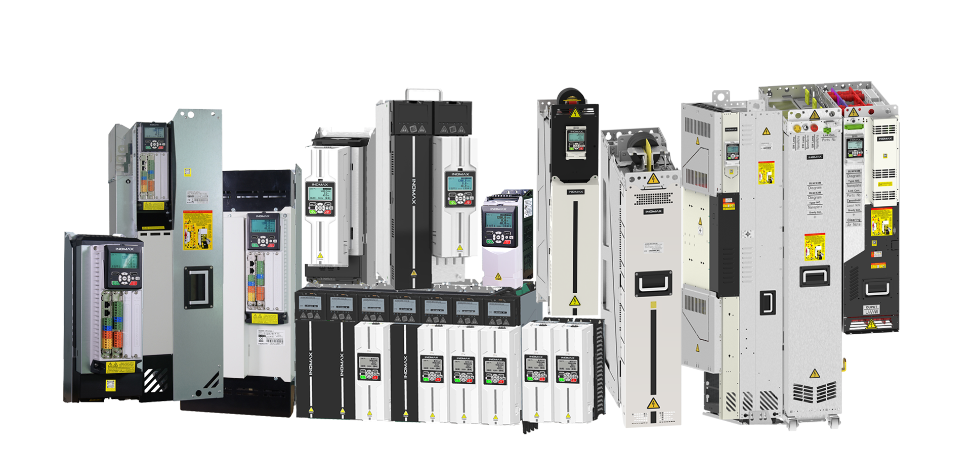
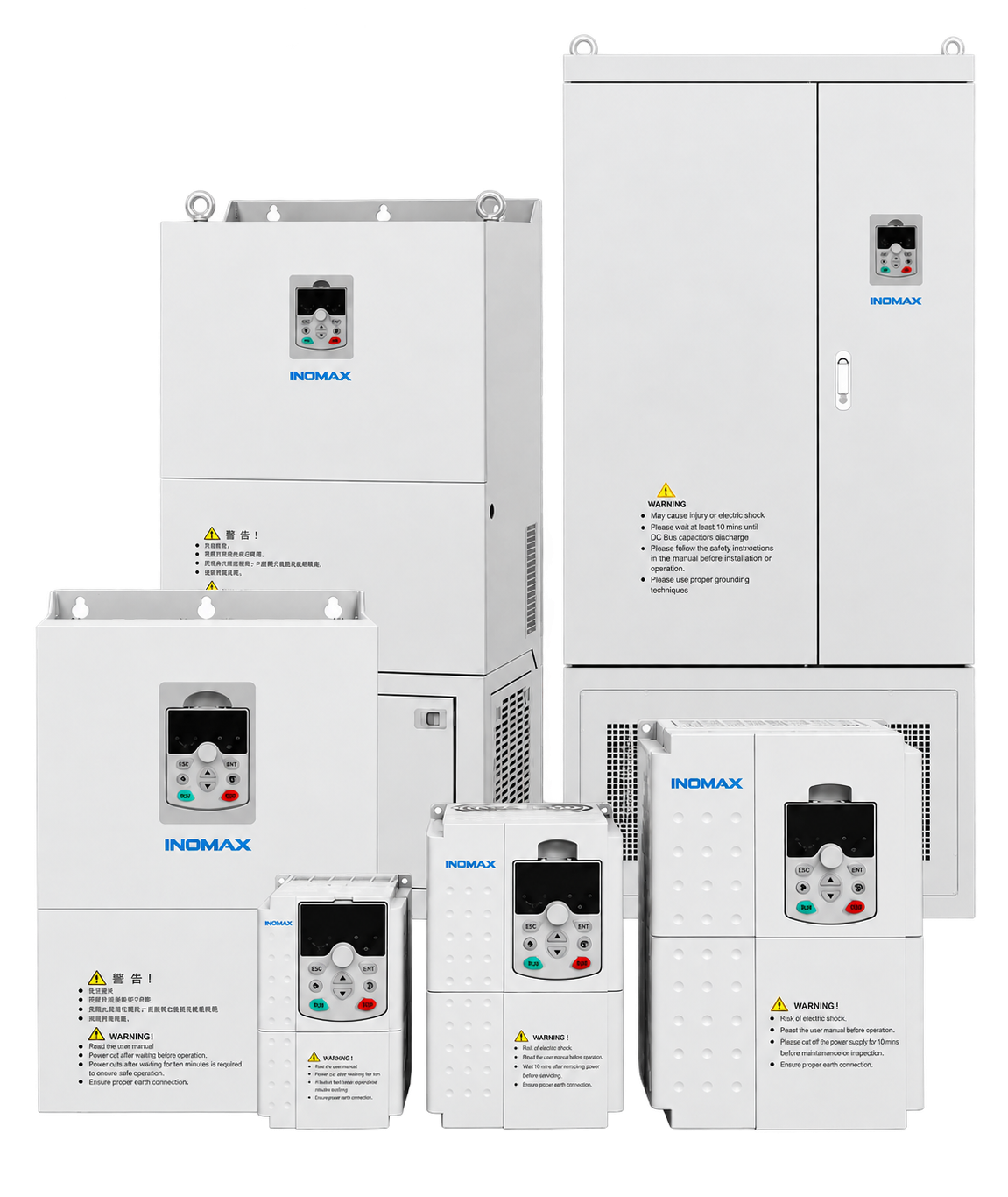
INOMAX supplies MAX and ACS drive families for different motor-control requirements. MAX500 is a starting point for general-purpose applications; MAX510 addresses higher-performance requirements; MAX600 focuses on HVAC applications. ACS industrial drive configurations are evaluated for demanding applications involving torque control, regeneration, modular systems or liquid cooling. Confirm every function against the selected model and options.
Project examples help connect the technology to a real engineering task:
- Indonesian steel mill modernization: conversion from DC to AC drive technology for multi-motor roller conveyors.
- Marine liquid-cooled drive retrofit: replacement planning around the existing vessel installation.
- 690 V regenerative mine hoist drive: a lifting application with engineered energy-flow requirements.
These cases describe particular projects. Their configurations, savings and delivery conditions should not be assumed to apply unchanged to a different installation.
Frequently Asked Questions About VFDs
Is a VFD the same as an inverter?
In motor-control discussions, “inverter” often means the complete drive. Technically, the inverter is the stage that converts DC into controlled AC. Confirm the intended equipment when discussing specifications.
Can a VFD operate any AC motor?
No. Check the motor type, insulation, cooling, speed limits and drive control support. Specialized motors need their own compatibility review.
Does a VFD change voltage as well as frequency?
Yes. The drive coordinates its output according to the control strategy and motor requirements. The available output voltage remains limited by its supply and topology.
Can a 50 Hz motor run at 60 Hz?
Only after checking the motor and machine’s permitted operating conditions. Increased speed changes mechanical duty, and available torque may be limited by voltage and field weakening.
Can one VFD run multiple motors?
Some applications permit this, but control mode, combined current, individual motor protection and switching arrangements must be designed accordingly. Independent motor-speed control generally requires separately controlled outputs.
Does every VFD return energy to the grid?
No. A regenerative supply interface is required for controlled energy return to the grid. A standard diode-input drive does not provide this capability by itself.
Does STO hold a suspended load?
Safe torque off does not provide a mechanical holding brake. A lifting system requires its own engineered stopping and holding strategy, with any claimed safety function verified for the actual equipment.
What information should I send for a quotation?
Send the motor nameplate, supply voltage, machine description, duty cycle, speed range, braking needs, installation conditions and control interfaces to info@inomaxtechnology.com.