
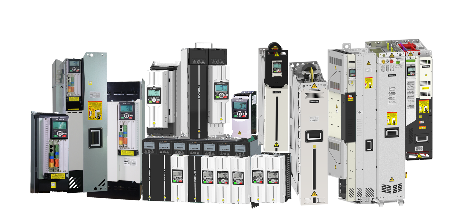

A common DC bus connects compatible motor inverter sections to a shared DC supply. One axis can use energy returned by another axis when their operating cycles overlap. Net surplus braking energy still needs an engineered path, such as regeneration or a braking resistor.

What is a common DC bus drive system?
A typical variable frequency drive has a supply-side rectifier, a DC link and a motor-side inverter. In a modular multi-drive system, several inverter sections use a common DC link instead of each having a completely separate AC-input front end.
The architecture separates two engineering questions: how each motor is controlled, and how electrical power is supplied or recovered. It can suit coordinated production lines, winding systems, roller conveyors and test equipment with multiple motor axes.
Understand the energy balance
Consider an illustrative instant when a winding axis returns 30 kW to the DC bus and another axis needs 50 kW. Ignoring conversion losses, the supply would need to provide about 20 kW. This is an explanation of power flow, not a measured INOMAX project result.
If the motoring axis stops consuming power while the other continues braking, the returned energy cannot simply disappear. The system must control the DC voltage using the selected energy-handling arrangement. A common bus can reduce the energy that needs external handling, but it does not guarantee that a resistor or regenerative supply is unnecessary.
Separate drives or a modular common bus?
| Project question | Independent AC-input drives | Engineered common DC bus |
|---|---|---|
| How are motors supplied? | Each drive normally has its own front end. | Motor inverter sections share a DC source. |
| Can axes exchange braking energy? | Not automatically between independent DC links. | Yes, when compatible equipment and the operating cycle allow it. |
| What determines supply sizing? | Each drive duty and the overall AC demand. | Simultaneous axis power, losses, peak duty and regenerative balance. |
| What happens during a fault? | Assess the individual drive and upstream protection. | Assess shared-bus protection, selectivity and effects on other axes. |
| What determines process synchronization? | Motor controls, PLC/network and feedback. | Still the controls, PLC/network and feedback—not the shared power bus alone. |
What needs to be engineered?
- Voltage compatibility: verify the DC operating range of all connected power sections and any supply options.
- Precharge and sequencing: define how the DC capacitance is charged and how each section is enabled or isolated.
- Protection: assess fault current, busbars, fuses, isolation and the consequences of a shared-bus fault.
- Operating cycles: obtain speed, torque and power profiles for every axis, including simultaneous starts and stops.
- Braking path: size regeneration or resistor equipment for the net surplus and the relevant peak conditions.
- Motor control: define speed references, torque sharing, encoder feedback, network timing and process interlocks.
Do not connect the DC terminals of unrelated drives simply because their motor voltage ratings look similar. The manufacturers’ approved configurations and the engineered system drawings must support the connection.
When does a common bus make sense?
Start with a power-versus-time study. A line with one axis braking while others motor presents a different opportunity from a machine where all axes accelerate and brake together. Consider the process control needs, cabinet layout, service strategy and future expansion as well as energy use.
On a winder, for example, changing roll diameter affects speed and torque requirements. On a roller line, different motor groups may have different load cycles. A shared bus does not remove the need to rate each motor inverter for its own continuous and peak current.
Where INOMAX ACS890 fits
INOMAX presents ACS890 modular drive systems for common-DC-bus and multi-motor integration. For a quotation, provide the number of axes, motor data, speed/torque profiles, PLC and feedback requirements, cooling arrangement and available supply.
The Indonesian steel-mill regenerative drive project is a related reference for multi-motor modernization. Use its engineering context to discuss a new project, rather than assuming its layout applies unchanged.
Frequently asked questions
Does a common DC bus automatically regenerate to the grid?
No. Sharing energy on a DC bus and returning energy to the AC supply are different functions. The selected supply-side converter determines line regeneration.
Does a common bus synchronize motor speeds?
No. The bus distributes power. Coordinated speed or torque control requires suitable control functions, communications and feedback.
Can the rectifier be smaller than the total motor power?
Possibly, if the simultaneous power profile supports it. Peak conditions, overload, losses and operating combinations must be assessed before selecting a rating.