



Three-level conversion
Selected to address harmonics, dv/dt and voltage stress in the high-speed PM application.

POWER GENERATION · ENGINEERING CASE
High-speed PM generator · Three-level conversion · INOMAX ACS890
A liquid-cooled converter proposal connecting a high-speed permanent-magnet generator to a 690 V, 50 Hz grid, with coordinated control and fault-energy management.
01 / PROJECT OVERVIEW
A high-speed permanent-magnet generator requires more than a conventional motor-drive selection.
The application calls for active generator speed control and conversion of generated electrical energy into a fixed-voltage, fixed-frequency grid supply. INOMAX’s ACS890 proposal coordinates the generator-side converter, grid-side AFE, liquid cooling and braking branch.
The generator is rated at 3,000 kW and 8,000 rpm. The proposal separately defines the generating duty as up to 2.5 MW. This engineering case explains the selection and integration approach for that duty.
02 / ENGINEERING REQUIREMENTS
03 / INOMAX SOLUTION
The proposed ACS890 architecture separates application control from the power units while coordinating the complete energy path.
Selected to address harmonics, dv/dt and voltage stress in the high-speed PM application.
Four 900 kW AFE modules provide 3.6 MW of installed module capacity before application-specific limits.
A separate braking branch and UPS-backed controls support the proposed stopping strategy.
Parallel coolant paths and thermal supervision are considered together with cabinet design.
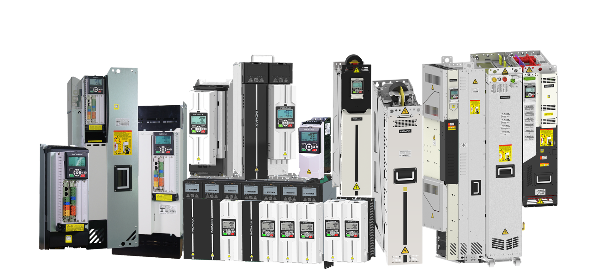
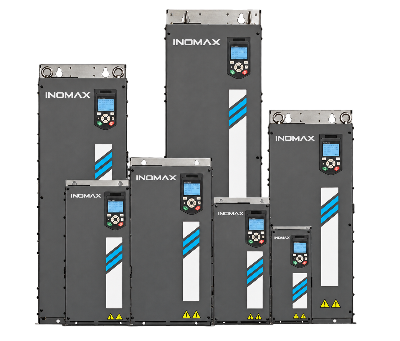
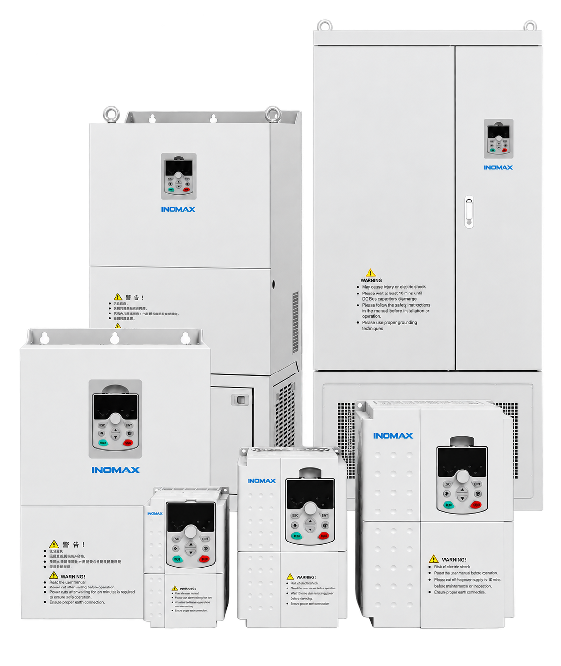
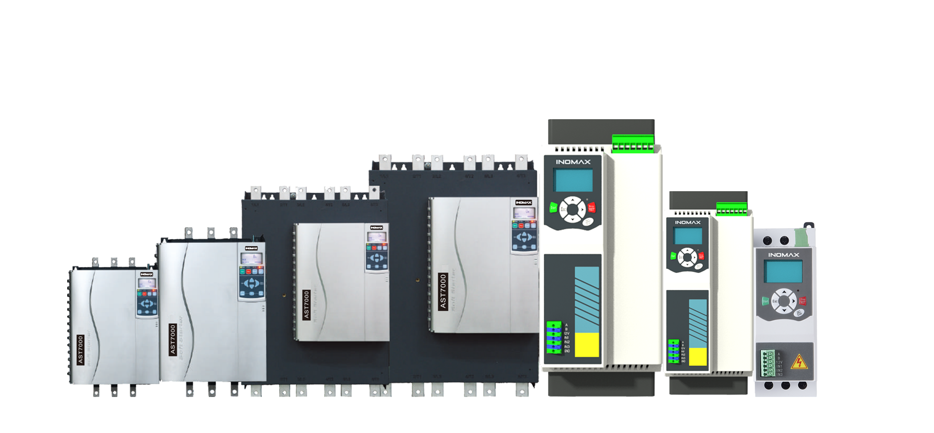
Conceptual cabinet and platform views from the engineering proposal. The control-platform illustration is not an equipment quantity schedule.
→
→
→
The generator-side converter controls speed; the AFE maintains DC-link voltage. Steam flow determines generated power after the startup torque limit is released.
The proposed sequence closes the steam valve and directs surplus energy to the braking resistor while generator control remains available. UPS-backed control supports the blackout stop sequence.
04 / TECHNICAL DATA
Selected application and equipment data from the ACS890 engineering proposal.
| Parameter | Project design basis |
|---|---|
| Machine type | High-speed permanent magnet |
| Rated power / current | 3,000 kW / 2,828 A |
| Voltage / phases | ≤690 V / 3-phase |
| Rated speed / frequency | 8,000 rpm / 266.7 Hz |
| Rated efficiency / duty | ≥96.4% / S1 continuous |
| Control requirement | Sensorless open-loop operation |
| Defined generating duty | Up to 2.5 MW |
| Parameter | Proposal value |
|---|---|
| Grid connection | 690 V / 50 Hz |
| AFE installed module capacity | 4 × 900 kW = 3.6 MW |
| Peak braking module capacity | 2 × 1,800 kW = 3.6 MW |
| Pure-water cabinet flow | ≥410 L/min |
| 80:20 water / glycol flow | ≥440 L/min |
| Cooling inlet temperature | 28–38 °C |
| Operating pressure | 2–6 bar |
Efficiency is the generator nameplate specification. Installed module capacity and peak braking capacity are not continuous plant-output ratings. Cooling-unit selection is subject to the final heat-duty and hydraulic checks.
| Equipment | INOMAX model | Rating / role | Qty. |
|---|---|---|---|
| Liquid-cooled AFE | ACS890-T821-0761-7 | 900 kW / 690 V | 4 |
| Generator-side inverter | ACS890-T83-1123-9 | 1,400 kW at 900 V / 1,100 kW at 690 V | 4 |
| Braking module | ACS890-T834-1200-15 | 1,800 kW / 1,500 V DC | 2 |
| AC LC filter | SLC-270U-600-7-LA | Grid-side filtering | 4 |
| Balancing reactor | ACL-10U-1000 | Parallel current sharing | 4 |
| Main control unit | CU200 | Separated control and power | 2 |
The equipment schedule is part of an engineering proposal. Final current ratings, cooling duty and stopping requirements are verified during detailed engineering.
05 / ENGINEERING VALUE
Selection goes beyond total kilowatts to address machine behaviour, grid conditions and stopping energy.
High speed, PM back EMF and the overspeed requirement shape voltage margin and converter selection.
The proposed control sequence links steam-valve closure, generator deceleration, the braking branch and UPS-backed controls.
Liquid-cooled modules, parallel circuits and cabinet requirements define the thermal interface for the complete system.
06 / ENGINEERING TOOLS & RECORDS
Reference equipment and technical illustrations accompany the engineering proposal.
PROFINET, EtherCAT, EtherNet/IP, Modbus TCP and CANopen options described in the platform proposal.
Parameter access, fault review and waveform tools support commissioning and troubleshooting.
This is a proposal-stage case. Reference images and software waveforms are not site acceptance results.
FOR YOUR NEXT PROJECT
For steam turbine OEMs, generator manufacturers, power-system integrators and industrial plant engineering teams.
Match a converter to the generator’s speed, current, voltage and overspeed envelope. Define control responsibility between the turbine and electrical package.
Coordinate grid connection, plant PLC or DCS interfaces, cooling and fault handling. Establish the converter supplier’s scope and the site acceptance plan.
Evaluate a replacement converter or a new waste-heat generation package using the existing generator and plant data. Compare engineering scope, protection and lifecycle support.
This reference shows the ACS890 engineering approach through a generator schedule, converter selection, cabinet arrangement and protection concept. It is a proposal-stage reference; operating results are not claimed.
07 / YOUR APPLICATION QUESTIONS
Generator compatibility, converter replacement, grid connection and protection for your project.
Start with your application. Use these answers to identify what can carry over, what needs engineering and what to confirm before ordering.
INOMAX can evaluate an alternative converter package for an existing turbine-generator system. The replacement review covers generator type, speed and voltage envelope, continuous current, grid-side functions, control ownership and fault protection. Provide the original converter specifications, generator data and plant diagrams. Existing equipment can be retained where compatible, but matching a brand’s headline kW rating does not establish an interchangeable converter or control system.
Yes, a project-specific selection can be evaluated for another high-speed PM generator. Required data include pole count, rated and maximum speed, electrical frequency, current, back-EMF curve, inductance, insulation limits and feedback requirements. A generator with the same power can impose very different voltage and switching requirements. The 8,000 rpm machine in this proposal provides a design example, not a universal speed or frequency limit.
INOMAX can review different power levels using an application-specific converter and module arrangement. Continuous electrical output, generator current, overload duty, voltage, cooling and grid-side capacity determine the selection. Installed module capacity must not be treated as guaranteed plant output. This reference uses a 3 MW-nameplate generator with a separately defined generating duty of up to 2.5 MW; a different duty requires a new electrical and thermal check.
Different grid voltages and frequencies can be assessed during system design. Generator-side voltage and grid-side voltage must be considered separately, together with converter ratings, DC-link limits, filters, protection and any transformer. This proposal specifies 690 V, 50 Hz. A 400 V or 60 Hz requirement should be included at enquiry stage so the grid interface is engineered for that network rather than assumed compatible with the reference design.
It is relevant to projects that need controlled conversion between a variable-frequency generator and an electrical supply, including suitable steam-based waste-heat recovery and combined heat and power (CHP) applications. Feasibility depends on the generator, turbine operating range, required controls and grid connection. Other prime movers or generator technologies require their own review. This case demonstrates an engineering approach; it does not establish a completed installation in every adjacent application.
A three-level topology is worth evaluating when machine voltage, switching stress, harmonics or a high-speed generator’s insulation requirements make waveform quality especially important. The choice must consider motor-side dv/dt, electrical frequency, cooling, filters and total system complexity. INOMAX selected three-level conversion for this PM-generator proposal. Another machine may need a different topology; the selection should follow generator and grid requirements rather than power rating alone.
Grid-connected, islanded and black-start operation require different control and protection functions. This engineering case addresses grid-connected generation and should not be treated as proof of grid-forming or black-start capability. If island operation is required, specify how voltage and frequency will be established, how loads are shared, the available starting energy and the transfer sequence. INOMAX can review the additional scope with the turbine and plant-control suppliers.
The protection concept must address continuing turbine input, rotor energy, generator back EMF and the loss of a grid export path. In the proposed approach, steam-valve closure, controlled deceleration and a braking branch are coordinated, with UPS-backed controls for the intended stop sequence. Braking energy and thermal duty need calculation; a peak braking-module rating alone does not establish stopping capability. Independent turbine protection and mechanical overspeed protection remain part of the overall system design.
The existing cooling system can be assessed against converter heat loss, coolant quality, temperature, flow, pressure and materials compatibility. A liquid-cooled arrangement is used in this proposal. If air cooling is preferred, the power-module selection, ventilation demand, ambient conditions and cabinet space must be reviewed as a different design. Cooling-unit supply and the boundary between internal and plant-side circuits should be stated explicitly in the quotation.
The control architecture can be developed around agreed speed, power and torque commands, status feedback, trips and interlocks. Define which controller owns each operating mode and how the system behaves after a communication failure. The platform proposal describes PROFINET, EtherCAT, EtherNet/IP, Modbus TCP and CANopen options; the selected hardware and protocol must be confirmed for the actual project. Interface mapping and acceptance tests belong in the engineering scope.
Compliance must be defined against the installation country, utility requirements and selected equipment. Request the applicable product certificates and test reports, and agree the site-specific harmonic, protection, EMC and grid-connection requirements before ordering. An AFE or low-harmonic topology alone does not establish utility approval. The proposal should allocate responsibility for network studies, protection settings, required tests and final acceptance, rather than assume that a reference design is pre-approved for every grid.
Provide the generator data and back-EMF curve, turbine operating and trip requirements, grid information, load profile, cooling conditions, control interfaces and target schedule. Compare converters on continuous duty, fault-energy handling, filters, cabinet and cooling scope, engineering documentation, FAT, commissioning responsibilities, spare parts and warranty. INOMAX can discuss a defined converter package within the wider turbine project; turbine, generator, civil works and site services should each have an explicit scope owner.
CUSTOMER PRIVACY & CONFIDENTIALITY
To respect our customers’ privacy and confidentiality commitments, selected customer identities, original drawings and project-specific information are not published. INOMAX works with customers under confidentiality agreements where applicable.
If you are evaluating a similar application, contact the INOMAX sales team. We welcome technical discussions and can share further relevant information within the limits of our confidentiality obligations.
LET’S DISCUSS YOUR APPLICATION
Share the generator data, speed and voltage range, grid requirements and project schedule. We’ll discuss the electrical design, protection concept and converter supply scope.
Project-specific drive and power conversion systems